Download
1 / 27
270 likes | 433 Vues
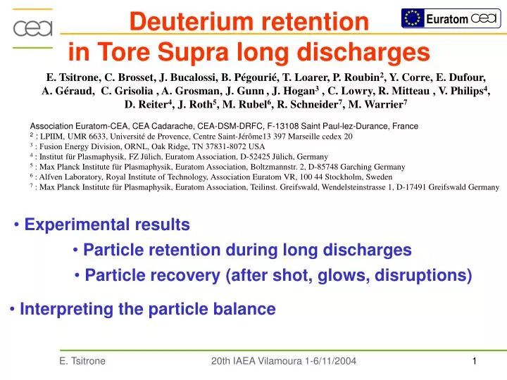
Deuterium retention in Tore Supra long discharges. E. Tsitrone, C. Brosset, J. Bucalossi, B. Pégourié, T. Loarer, P. Roubin 2 , Y. Corre, E. Dufour, A. Géraud, C. Grisolia , A. Grosman, J. Gunn , J. Hogan 3 , C. Lowry, R. Mitteau , V. Philips 4 ,

E N D
Deuterium retention in Tore Supra long discharges E. Tsitrone, C. Brosset, J. Bucalossi, B. Pégourié, T. Loarer, P. Roubin2, Y. Corre, E. Dufour, A. Géraud, C. Grisolia , A. Grosman, J. Gunn, J. Hogan3 , C. Lowry, R. Mitteau , V. Philips4, D. Reiter4, J. Roth5, M. Rubel6, R. Schneider7, M. Warrier7 Association Euratom-CEA, CEA Cadarache, CEA-DSM-DRFC, F-13108 Saint Paul-lez-Durance, France 2 : LPIIM, UMR 6633, Université de Provence, Centre Saint-Jérôme13 397 Marseille cedex 20 3 : Fusion Energy Division, ORNL, Oak Ridge, TN 37831-8072 USA 4 : Institut für Plasmaphysik, FZ Jülich, Euratom Association, D-52425 Jülich, Germany 5 : Max Planck Institute für Plasmaphysik, Euratom Association, Boltzmannstr. 2, D-85748 Garching Germany 6 : Alfven Laboratory, Royal Institute of Technology, Association Euratom VR, 100 44 Stockholm, Sweden 7 : Max Planck Institute für Plasmaphysik, Euratom Association, Teilinst. Greifswald, Wendelsteinstrasse 1, D-17491 Greifswald Germany • Experimental results • Particle retention during long discharges • Particle recovery (after shot, glows, disruptions) • Interpreting the particle balance
Outboard movable limiter Bumpers Shadowed zones Toroidal pump limiter (TPL) CCD imaging of the TPL Plasma loaded zones • 15 m2 of carbon plasma facing components • Active cooling : stationary PFC temperature from 120°C (cooling loop) up to 250°C on the limiter for long pulses • Active pumping : neutralisers below TPL Tore Supra : the CIEL configuration • Long pulse : LH driven discharge at Vloop~ 0, low plasma current/density • low density hot edge plasma (Te ~ 100 eV at the LCFS)
Particle retention in long discharges Phase 2 Phase 1 • Phase 1 (~ 100 s) • Decreasing retention rate • Phase 2 • Constant retention rate (= 50% of injected flux) • No saturation after 6 minutes • In vessel inventory • shot duration in phase 2 (Imax = 8 1022 D for 6 minutes) • Identical shot to shot behaviour No saturation of in vessel retention after 15 minutes of cumulated plasma time
Particle recovery after shot Retention phase 1 ~ 100 s Phase 1 Phase 2 x 1022 x 1021 • Small fraction recovered after shot • Recovery correlated to retention in phase 1 : transient retention mechanism • Recovery > plasma content : • the wall releases particles
Recovery after disruption : up to 5 1022 D < Imax • Large scatter at given Ip : machine history dependent ? • (highest exhaust in start up phase) Particle recovery after glow discharge and disruptions • Recovery after He glow discharge (6 hours): 1.5 - 2 1022 D < Imax • Independent of the quantity trapped during the day of experiment • Threshold in Ip : • Ip < 0.8 MA : ~ after shot recovery • Ip > 0.8 MA : increase with Ip dissipated energy high enough to heat D rich deposited layers • [D. Whyte, PSI 2004]
Sample analysis : D content Net deposition zone Shadowed Plasma facing Net erosion zone (main plasma interaction area) Carbon deposits Several mms TPL < 1 mm Several mms Net deposition zones Outboard limiter Neutraliser finger Cold deposits (~ 120 °C) D/C ~ 10 % ND~ 1022 at /m2 / mm * S * d Hot deposits (> 500°C) D/C ~ 1 % ND~ 1021 at/m2 * S [C. Brosset, PSI 2004] TPL deposits analysis still in progress Cold deposits in shadowed areas D reservoir
Implantation D C D+, D0 Progressive saturation of bombarded surfaces (D+, D0) until CDmax reached Carbon dimp< 0.1 mm D0 D2 D2+ Phase 1 Bumpers D+ TPL [E. Tsitrone, PSI 2004] Interpreting the particle balance Saturation time : from ~ 1s (TPL) to ~ 100 s (bumpers) BUT : does not explain shot to shot behaviour unless very strong diffusion takes place
Interpreting the particle balance • Filling the CFC porosity D2, D0 5 1021 D Phase 1 • Extrapolation from lab exp (77 K) : • 1022 D/g deposits 0.5 g enough to account for phase 1 Adsorption M. Warrier et al., Contrib. Plasma Phys. 44, No. 1-3, (2004) • TS deposited layers : 100 times more porous than original CFC • [P. Roubin, PSI 2004] • Adsorption : weak bond ( chemical bond) • ok for transient mechanism • Outgassing after shot ~ phase 1 duration ( ~ 100s) : • ok with filling / emptying the porosity reservoir Good candidate for phase 1 BUT : extrapolation from lab to tokamak environment (temperature)
Interpreting the particle balance • Codeposition : physical sputtering chemical sputtering Phase 1 + 2 Distant redeposition (TPL shadowed areas, neutralisers, outboard limiter …) C, D Carbon deposits 5 1020 C6+/s Erosion CxDy 6 1020 C/s (phys. + self) • 1.5 1020 CD4/s (chem.) 1020 C/s Local redeposition 1.5 1020 CD4/s • Preliminary estimates of carbon erosion sources • physical + chemical sputtering by D+ and D0 • self sputtering by Cn+ (assumed 5% C in D+ flux) • ok with Zeff, ok with low net erosion on TPL (high local redeposition), ok with layers growing rate carbon balance roughly coherent
Interpreting the particle balance • Codeposition : D balance 2 1020 D/s Phase 1 + 2 • 1/3 of produced CD4 trapped : • but high D/C ratio film : not observed Distant redeposition (TPL shadowed areas, neutralisers, outboard limiter …) Erosion 6 1020 C/s 5 1020 C6+/s • 1.5 1020 CD4/s 1020 C/s 1.5 1020 CD4/s Local redeposition • If D/C = 0.1 : need 2 1021 C/s of net redeposition : high erosion/redeposition on TPL ( > 100 mm on 4 m2):not observed • No coherence between D retention rate / D/C ratio / C erosion/redeposition D rich film created during the discharge subsequently depleted in D (glows, disruptions) ? Hard to explain the retention rate in phase 2 with codeposition alone
Summary Transient retention : recovered after shot Permanent retention : NOT recovered after shot Phase 1 Phase 2 • D retention : no wall saturation after 15 minutes in high Te / low ne edge plasma • D recovery (He glow discharge, disruptions) < in vessel inventory accumulated in a single long discharge • Codeposition of D and C : • Can hardly explain the retention rate in phase 2 • D implantation in C : • progressive saturation but not transient • D content sample analysis : • D mainly in cold deposits in shadowed areas (120 °C) • D adsorption in porosity : • good candidate, but to be assessed in tokamak environment Missing D not found yet but still a lot to investigate (TPL deposits, pumping ducts …)
D+ to pumps Tore Supra : well equipped for particle balance dNp/dt = Finj – Fpump –F in vessel • Gas injection : manometers • Active pumping : 10 neutralisers with turbo-molecular pumps equipped with 20 pressure gauges (1 in vertical port, 1 at the pump) + 2 Penning gauges (D2/He) + mass spectrometer • 2 pressure gauges in the chamber (equatorial ports) • pressure gauges in primary exhaust system • Systematic calibration procedure : calibrated gas injection in the chamber with/without pumps activated
Effect of active pumping Shifted gas injection Pumping on Pumping off Active pumping on Tore Supra : no effect on dynamic wall retention but offset on gas injection Same wall inventory
Particle balance sensitive to LH power loss LH power (MW) Shot 32299 Injected flux (Pa.m3/s) Extracted Flux (Pa.m3/s) Gas Puffing Inventories (Pa.m3) Vessel Inventory TPL exhaust Plasma Content x100 Vessel Exhaust s Time (s) dNp/dt = Finj – Fpump –F in vessel
Disruption heats deposited layers Plasma loaded zones DT (°C) before/after disruption (20 ms) Net erosion zone (main plasma interaction area) Shot 33067 CCD imaging of the TPL DT > 220 °C Shadowed zones Thickest deposition zone (shadowed/plasma area) Moderate deposition zone (plasma interaction area)
IR shows cold deposits T°C #33067 (t-20ms) T #33067 (disruption)
D inventory in the machine Estimated D inventory in the machine : From analysed samples : ~ 5 1022 D (80% in cold deposits) From non analysed samples (TPL surface) : ~ 4 1022 D (most of it in TPL shadowed zones) Total : ~ 9 1022 D BUT : surface/depth of layers difficult to assess, samples still to be analysed Estimated D inventory from particle balance integrated over a campaign: From averaged net retention rates : ~ 1.5 1024 D Glow discharge : ~ 4 1023 D Disruptions : ~ 3 1023 D Total : ~ 8 1023 D BUT : retention rate scenario dependent, not all disruptions recorded, glow D2 not accounted, cleaning discharges … No firm conclusion can be drawn on D balance
Deuterium retention in Tore Supra long discharges E. Tsitrone, C. Brosset, J. Bucalossi, B. Pégourié, T. Loarer, P. Roubin2, Y. Corre, E. Dufour, A. Géraud, C. Grisolia , A. Grosman, J. Gunn, J. Hogan3 , C. Lowry, R. Mitteau , V. Philips4, D. Reiter4, J. Roth5, M. Rubel6, R. Schneider7, M. Warrier7 Association Euratom-CEA, CEA Cadarache, CEA-DSM-DRFC, F-13108 Saint Paul-lez-Durance, France 2 : LPIIM, UMR 6633, Université de Provence, Centre Saint-Jérôme13 397 Marseille cedex 20 3 : Fusion Energy Division, ORNL, Oak Ridge, TN 37831-8072 USA 4 : Institut für Plasmaphysik, FZ Jülich, Euratom Association, D-52425 Jülich, Germany 5 : Max Planck Institute für Plasmaphysik, Euratom Association, Boltzmannstr. 2, D-85748 Garching Germany 6 : Alfven Laboratory, Royal Institute of Technology, Association Euratom VR, 100 44 Stockholm, Sweden 7 : Max Planck Institute für Plasmaphysik, Euratom Association, Teilinst. Greifswald, Wendelsteinstrasse 1, D-17491 Greifswald Germany ITER in vessel T inventory limit : (retention rate - recovery rate) dt < 350 g • minimize the retention rate • optimize the recovery techniques • Experimental results • Particle retention during long discharges • Particle recovery (after shot, glows, disruptions) • Interpreting the particle balance
Particle retention in long discharges Phase 2 Phase 1 dNp/dt = Finj – Fpump –F in vessel • Phase 1 (~ 100 s) • Decreasing retention rate • Phase 2 • Constant retention rate (= 50% of injected flux) • No saturation after 6 minutes • In vessel inventory • shot duration in phase 2 (Imax = 81022 D for 6 minutes) • Identical shot to shot behaviour No saturation of in vessel retention after 15 minutes of cumulated plasma time
Sample analysis : D content Net erosion zone (main plasma interaction area) Net deposition zone Shadowed Plasma facing Carbon deposits Several mms TPL < 1 mm Several mms Moderate deposition zone (plasma interaction area) Outboard limiter Thickest deposition zone (shadowed area) Neutraliser finger Cold deposits (~ 120 °C) D/C ~ 10 % ND~ 1022 at /m2 / mm * S * d Hot deposits (> 500°C) D/C ~ 1 % ND~ 1021 at/m2 * S [C. Brosset, PSI 2004] TPL deposits analysis still in progress Cold deposits in shadowed areas D reservoir D content in analysed samples < D inventory over campaign
Interpreting the particle balance • Codeposition : Estimates of carbon erosion sources Phase 1 + 2 Distant redeposition (TPL shadowed areas, neutralisers, outboard limiter …) C, D Carbon deposits Erosion CxDy 6 1020 C/s 5 1020 C6+/s • 1.5 1020 CD4/s 1020 C/s 1.5 1020 CD4/s Local redeposition • C source underestimated : no synergy D+/D0, no localised hot Tsurf, no LH accelerated e- • ok with Zeff, ok with high redeposition (low net erosion on TPL), ok with layers growing rate • carbon balance roughly coherent
Sample analysis : D content Net erosion zone Net deposition zone Plasma facing Shadowed Plasma facing Carbon substrate Carbon deposits Several mms < 1 mm < 1 mm cold deposits Several mms hot deposits TPL Neutraliser finger TPL deposits analysis still in progress Cold deposits in shadowed areas Outboard limiter Hot deposits (> 500°C) D/C ~ 1 % ND~ 1021 at/m2 * S [C. Brosset, PSI 2004] Cold deposits (~ 120 °C) D/C ~ 10 % ND~ 1022 at /m2 / mm * S * d
Interpreting the particle balance • Filling the CFC porosity D2, D0 • TS deposited layers : 100 times more porous than virgin CFC • [P. Roubin, PSI 2004] 5 1021 D • Extrapolation from lab exp : • 1022 D/g deposits 0.5 g enough to account for phase 1 Phase 1 Adsorption dpvessel/dt = Soutgas – Seff pvessel M. Warrier et al., Contrib. Plasma Phys. 44, No. 1-3, (2004) pvessel • Recovery ~ phase 1 duration : ok with filling / emptying the porosity reservoir Soutgas • Adsorption : weak bond • ( chemical bond) • ok for transient mechanism Good candidate for phase 1 BUT : extrapolation from lab to tokamak environment (temperature, pressure, incident particles)
Deuterium retention in Tore Supra long discharges E. Tsitrone, C. Brosset, J. Bucalossi, B. Pégourié, T. Loarer, P. Roubin2, Y. Corre, E. Dufour, A. Géraud, C. Grisolia , A. Grosman, J. Gunn, J. Hogan3 , C. Lowry, R. Mitteau , V. Philips4, D. Reiter4, J. Roth5, M. Rubel6, R. Schneider7, M. Warrier7 Association Euratom-CEA, CEA Cadarache, CEA-DSM-DRFC, F-13108 Saint Paul-lez-Durance, France 2 : LPIIM, UMR 6633, Université de Provence, Centre Saint-Jérôme13 397 Marseille cedex 20 3 : Fusion Energy Division, ORNL, Oak Ridge, TN 37831-8072 USA 4 : Institut für Plasmaphysik, FZ Jülich, Euratom Association, D-52425 Jülich, Germany 5 : Max Planck Institute für Plasmaphysik, Euratom Association, Boltzmannstr. 2, D-85748 Garching Germany 6 : Alfven Laboratory, Royal Institute of Technology, Association Euratom VR, 100 44 Stockholm, Sweden 7 : Max Planck Institute für Plasmaphysik, Euratom Association, Teilinst. Greifswald, Wendelsteinstrasse 1, D-17491 Greifswald Germany ITER in vessel T inventory limit : (retention rate - recovery rate) dt < 360 g • minimize the retention rate • optimize the recovery techniques • Experimental results • Particle retention during long discharges • Particle recovery (after shot, glows, disruptions) • Interpreting the particle balance
Recovery after disruption : up to 5 1022 D < Imax • Large scatter at given Ip : machine history dependent ? • (highest exhaust in start up phase) Particle recovery after glow discharge and disruptions • Recovery after He glow discharge (6 hours): 1.5 - 2 1022 D < Imax • Independent of the quantity trapped during the day of experiment • ~ desaturation of 15 m2 of carbon implanted with D for 300 eV incident He • Threshold in Ip : • Ip < 0.8 MA : ~ after shot recovery • Ip > 0.8 MA : increase with Ip dissipated energy high enough to outgas deposited layers • [D. Whyte, PSI 2004]
Implantation D C D+, D0 Progressive saturation of bombarded surfaces (D+, D0) at CDmax = f(Einc, Tsurf ) Carbon Saturation time : from ~ 1s (TPL) to ~ 100 s (bumpers) dimp< 0.1 mm D0 D2 D2+ Phase 1 Implantation of D0 in bumpers Bumpers D+ TPL [E. Tsitrone, PSI 2004] Interpreting the particle balance BUT : does not explain shot to shot behaviour unless very strong diffusion takes place