Download
1 / 9
130 likes | 360 Vues
8.3.1 Mold strength and stiffness . During molding process, plastic melt will produce stress and deformation on mold cavity. If the cavity wall thickness is not enough, when the stress exceeds the material allowable stress, the cavity may rupture due to inadequate strength.

E N D
8.3.1 Mold strength and stiffness During molding process, plastic melt will produce stress and deformation on mold cavity If the cavity wall thickness is not enough, when the stress exceeds the material allowable stress, the cavity may rupture due to inadequate strength If the cavity stiffness is not enough, elastic deformation will lead to flashing, deformation and demolding difficult 8.3 Cavity Wall Thickness and Bottom Thickness
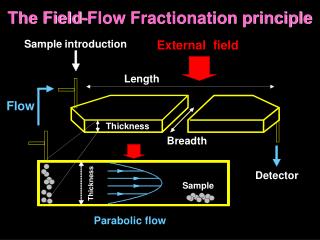
Clamping force exerted by the device molten plastic pressure on the cavity wall Affect the plastic parts dimensional accuracyflashing in the parting surface Low allowable deformation for Smallcavity, the pressure will lead to destruct on 8.3.2 force analysis of cavity wall 1.Mold force analysis during molding process 2. Cavity expansion and deformation by internal pressure Rectangular modular Thickness calculation
3. maximum allowable deformation of the cavity sidewall δ From the small and medium-sized plastic pieces of dimensional accuracy :δ≤Δ/5 Never produce flash fly side to consider: the value of the excess material of the cavity with the maximum clearance at the Zmax <plastic To ensure the smooth mold release for plastic parts: δ ≤ S. t (shrinkage) 8.3.2 force analysis of cavity wall Rectangular integral type cavity die and bottom plate
8.3.2 force analysis of cavity wall • To ensure dimension accuracy: δ≤Δ/5 • To ensure no flashing, the maximum clearance: Zmax﹤flashing • To ensure demolding:δ≤S·t • Stiffness standard for big cavity, strength standard for small cavity • Round cavity diameter D <67-86mm , using strength calculation • Rectangular cavity long side L <108-1136mm , using strength calculation Cavity mechanical calculations of the characteristics and nature of :
Cavity wall thickness value, using greater value in critical value 8.3.2 force analysis of cavity wall The cavity inner radius (mm) Cavity thickness by stiffness Cavity thickness by strength Thickness (mm) Stiffness Strength The cavity inner radius (mm)
Circular cavity wall thickness Rectangular cavity wall thickness Supporting plate thickness 8.3.3 Wall thickness calculation
3. Wall thickness calculations • Round cavity wall thickness calculation
3. Wall thickness calculations 2. Rectangle cavity wall thickness calculation Rectangular integral type cavity ※ Table wall thickness of the side length than the L / b = 1.8, the reference size, wall thickness should be appropriate to increase the L/b>1.8
3. Wall thickness calculations 3. calculation of supporting plate thickness ※ When the projected area of the plastic parts, supporting plate will be very thick, pillar can be added to reduce the thickness. By adding one pillars: H '= H/2.7 plus two pillars: H = H/4.3※ plate thickness values refer to Table