Download

1 / 56
580 likes | 894 Vues
Assembler language – 8051. Mairtin O Conghaile. 8051 Microcontroller. Complete, highly-integrated microcomputer CPU, RAM, ROM, IO Port 0 8-bit bidirectional I/O port OR multiplexed low-order address and data bus bytes Port 1 8-bit bidirectional I/O port Port 2

E N D
Assembler language – 8051 Mairtin O Conghaile
8051 Microcontroller • Complete, highly-integrated microcomputer • CPU, RAM, ROM, IO • Port 0 • 8-bit bidirectional I/O port OR • multiplexed low-order address and data bus bytes • Port 1 • 8-bit bidirectional I/O port • Port 2 • 8-bit bidirectional I/O port OR • high-order address byte • Port 3 • 8-bit bidirectional I/O port OR • various special-function signals
Introduction to the 8051 microcontroller • Type of memory • Code memory (64k max) • Internal RAM (128 bytes) • External RAM (64k max) • Special Function Registers (SFR) • Bit memory
Basic Registers • Accumulator • “R” registers • B register • Data Pointer (DPTR) – 16-bit register • Program Counter (PC) – 16-bit register • Stack Pointer (SP)
MOV instruction • Simply stated, the MOV instruction copies data from one location to another. It has the following format MOV destination, source • This instruction tells the CPU to move (copy) the source operand to the destination operand, without changing the content of the source operand. • Examples: • MOV A,#55h ; load 55h into register A • MOV R0,A ; copy contents of A into R0 • MOV R3, #95h ; load value 95h into R3 • MOV A,R3 ;copy content of R3 into A
Some useful pointers • Values can be loaded directly into any of the registers A,B or R0-R7. However, to indicate that it is an immediate value it must be preceeded with a # sign. MOV A,#23H ;load 23H into A MOV R6,#12 ;load 12d into R6 MOV R5,#0f9h • If value is small, rest of bits are assumed to be all zeros. E.g. mov a 4-bit value into an 8-bit register • Moving a value that is too large into a register will cause an error. • To load a value into a register it must be preceeded with a # sign. Otherwise it means to load from a memory location. MOV A,#17h ≠ MOV A,17h
ADD instruction • The ADD instruction has the following format: ADD A, source ;Add the source operand to A • This tells the CPU to add the source byte to reg A and put the result in reg A
Example • Calculate the content of the accumulator after the program is executed on the 8051. • MOV R5,#25h • MOV R7,#34H • MOV A,#0 • ADD A,R5 • ADD A,R7
Addressing Modes • An "addressing mode" refers to how you are addressing a given memory location. • In summary, the addressing modes are as follows, with an example of each: • Immediate Addressing MOV A,#20h • Direct Addressing MOV A,30h • Indirect Addressing MOV A,@R0 • External Direct MOVX A,@DPTR • Code Indirect MOVC A,@A+DPTR • Each of these addressing modes provides important flexibility.
Immediate Addressing • Immediate addressing is so-named because the value to be stored in memory immediately follows the operation code in memory. That is to say, the instruction itself dictates what value will be stored in memory. MOV A,#20h • This instruction uses Immediate Addressing because the Accumulator will be loaded with the value that immediately follows; in this case 20 (hexidecimal). • Immediate addressing is very fast since the value to be loaded is included in the instruction. However, since the value to be loaded is fixed at compile-time it is not very flexible.
Direct Addressing • Direct addressing is so-named because the value to be stored in memory is obtained by directly retrieving it from another memory location. For example: MOV A,30h • This instruction will read the data out of Internal RAM address 30 (hexidecimal) and store it in the Accumulator. • Direct addressing is generally fast since, although the value to be loaded isnt included in the instruction, it is quickly accessable since it is stored in the 8051s Internal RAM. • It is also much more flexible than Immediate Addressing since the value to be loaded is whatever is found at the given address--which may be variable. • Also, it is important to note that when using direct addressing any instruction which refers to an address between 00h and 7Fh is referring to Internal Memory. Any instruction which refers to an address between 80h and FFh is referring to the SFR control registers that control the 8051 microcontroller itself.
Indirect Addressing • Indirect addressing is a very powerful addressing mode which in many cases provides an exceptional level of flexibility. MOV A,@R0 • This instruction causes the 8051 to analyze the value of the R0 register. The 8051 will then load the accumulator with the value from Internal RAM which is found at the address indicated by R0. • For example, lets say R0 holds the value 40h and Internal RAM address 40h holds the value 67h. When the above instruction is executed the 8051 will check the value of R0. Since R0 holds 40h the 8051 will get the value out of Internal RAM address 40h (which holds 67h) and store it in the Accumulator. Thus, the Accumulator ends up holding 67h.
Indirect Addressing(cont’d) • Indirect addressing always refers to Internal RAM; it never refers to an SFR. Thus, in a prior example we mentioned that SFR 99h can be used to write a value to the serial port. Thus one may think that the following would be a valid solution to write the value 1 to the serial port: MOV R0,#99h ;Load the address of the serial portMOV @R0,#01h ;Send 01 to the serial port -WRONG!! • On an 8051 these two instructions would produce an undefined result since the 8051 only has 128 bytes of Internal RAM.
External Direct Addressing • External Memory is accessed using "External Direct" addressing. • There are only two commands that use External Direct addressing mode: MOVX A,@DPTR MOVX @DPTR,A • As you can see, both commands utilize DPTR. • In these instructions, DPTR must first be loaded with the address of external memory that you wish to read or write. Once DPTR holds the correct external memory address, the first command will move the contents of that external memory address into the Accumulator. • The second command will do the opposite: it will allow you to write the value of the Accumulator to the external memory address pointed to by DPTR.
External Indirect Addressing • External memory can also be accessed using a form of indirect addressing. • This form of addressing is usually only used in relatively small projects that have a very small amount of external RAM. An example of this addressing mode is: MOVX @R0,A • Once again, the value of R0 is first read and the value of the Accumulator is written to that address in External RAM. Since the value of @R0 can only be 00h through FFh the project would effectively be limited to 256 bytes of External RAM.
Question 1 • Write a short program for the 8051 microcontroller that carries out the following instructions: • Loads the accumulator with the value 40h • Loads R7 with 12d • Copies the content of R7 to address 30h directly • Loads the register R0 with 30h • Indirectly moves the contents of 30h to reg B • Indicate clearly the contents, at each stage, of all memory locations and registers involved.
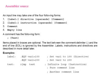
Structure of Assembly language • Consists of a series of assembly language instructions. • Instruction consists of four fields: [label1:] mnemonic [operands] [;comment] • Label field allows the program to refer to a line by name. • Comment field must begin with a semicolon
Example of Assembly Program ORG 0H ;start at mem loc 0 MOV R5,#25h ;load 25h in r5 MOV R7,#34H ;load 34h into r7 MOV A,#0 ;clear A ADD A,R5 ;A=A+R5 ADD A,R7 ;A=A+R7 ADD A,#12h ;A=A+12 HERE: SJMP HERE ;stay in this loop END ;end of asm source ;file
8051 Data Types and Directives • Only one type of data type – 8-bit • It’s the job of the programmer to break down data larger than 8-bits.
DB • The DB directive is the most widely used data directive in assembler. • Used to define the 8-bit data. • When DB is used, the numbers can be decimal, binary, hex or ASCII formats. • The only directive that can be used to define ASCII strings larger than two characters. ORG 500H DATA1: DB 39H DATA2: DB “2591” ;ASCII NUMBERS ORG 518H DATA3: DB “Computer Engineering”
Assembler Directives • ORG: Used to indicate the beginning of the address. • EQU: Used to define a constant without occupying a memory location. • e.g. Count EQU 25 • END: Indicates the end of the source file.
PSW (Program Status Word) • Addresses D0h, Bit-Addressable • The Program Status Word is used to store a number of important bits that are set and cleared by 8051 instructions. • The PSW SFR contains the carry flag, the auxiliary carry flag, the overflow flag, and the parity flag. • Additionally, the PSW register contains the register bank select flags which are used to select which of the "R" register banks are currently selected.
Example • State the contents of the RAM locations after the following program: SETB PSW.4 MOV R0,#99H MOV R1,#85H MOV R2,#99H MOV R7,#85H MOV R5,#99H
Solution • By default PSW.3 = 0 and PSW.4 =0; therefore line 1 sets RS1=1 and RS0 = 0, thereby selecting register bank 2. • Register Bank 2 uses RAM locations 10H – 17H. After execution of this program we have the following: • RAM location 10H has value 99H • RAM location 11H has value 85H • RAM location 12H has value 3FH • RAM location 17H has value 63H • RAM location 15H has value 12H
Stack in the 8051 • Section of RAM used by the CPU to store information temporarily. • Information can be data or an address. • The CPU needs this storage area since there are only a limited number of registers.
How stacks are accessed in the 8051 • The register used to access the stack is called the SP (stack pointer) and is 8-bits wide (00h-ffh). • When the 8051 is powered up the SP contains the value 07. • This means that RAM location 08 is the first location used for the stack. • Final location is 1F (20h -> used for bit- addressable memory) • Storing of a CPU register in the stack is called a PUSH. • Loading the contents of the stack back into a CPU register is called a POP.
Pushing onto the stack • The SP points to the last used location of the stack. • As we push data onto the stack, the stack pointer is incremented by one. • When you pop a value off the stack, the 8051 returns the value from the memory location indicated by SP, and then decrements the value of SP.
Example • Show the stack and stack pointer for the following: MOV R6,#25H MOV R1,#12H MOV R4,#0F3H PUSH 6 ;push onto stack from R6 PUSH 1 ;push onto stack from R1 PUSH 4 ;push onto stack from R4 POP 3 ;pop stack into R3 POP 5 ;pop stack into R5 POP 2 ;pop stack into R2
Upper Limit • Ram locations 08 – 1F used for the stack. • If more than 24bytes of stack required, then the SP must be changed to point to RAM locations 30h-7Fh using the instruction MOV SP,#xx • Also may need to shift SP if a given progam needs register bank1,2 or 3.
Example • Show the stack and stack pointer for the following instructions: MOV SP,#5FH MOV R2,#25H MOV R1,#12H MOV R4,#0F3H PUSH 2 PUSH 1 PUSH 4
Questions • Write a simple program in which the value 55h is added five times. • Show the stack and the stack pointer for each line of the following: Org 0 MOV SP,#70H MOV R5,#66H MOV R2,#7FH MOV R7,#5DH PUSH 5 PUSH 2 PUSH 7 CLR A MOV R2,A MOV R7,A POP 7 POP 2 POP 5
Program Flow • When an 8051 is first initialized, it resets the PC to 0000h. • The 8051 then begins to execute instructions sequentially in memory unless a program instruction causes the PC to be otherwise altered. • There are various instructions that can modify the value of the PC; specifically, conditional branching instructions, direct jumps and calls, and "returns" from subroutines. • Additionally, interrupts, when enabled, can cause the program flow to deviate from its otherwise sequential scheme.
Loop and Jump Instructions • Repeating a sequence of instructions a certain number of times is called a loop. • The loop action is performed by the instruction DJNZ reg,label • In this instruction, the register is decremented; if it is not zero, it jumps to the target address referred to by the label. • Prior to the start of the loop the register is loaded with the counter for the number of repetitions.
Example • Write a program to clear the Acc, then add 3 to the accumulator ten times. MOV A,#0 MOV R2,#10 AGAIN: ADD A,#03 DJNZ R2,AGAIN MOV R5,A
Question • Write a program to load the accumulator with the value 10h and then complement the Acc 700times. (Hint: Try two separate loops to achieve the overall of 700)
Solution MOV A,#10H MOV R3,#10 NEXT: MOV R2,#70 AGAIN: CPL A DJNZ R2,AGAIN DJNZ R3,NEXT
Example • Find the sum of the values 79H, F5H and E2H. Put the sum of the registers in R0 (low byte) and R5 (high byte)
Solution MOV A,#0 ;clear A MOV R5,A ;clear R5 ADD A,#79H ;A=A+79h JNC N_1 ;if no carry, add next INC R5 ;if CY=1, increment R5 N_1: ADD A,#0F5H ;A=79H+F5H=6EH and CY1=1 JNC N_2 ;jump if CY=0 INC R5 ;if CY=1, increment R5 N_2: ADD A,#0E2H ;A=6E+E2=50H and CY=1 JNC OVER ;jump if CY=0 INC R5 ;if CY=1, increment R5 OVER: MOV R0,A ;now R0=50H and R5=02
Unconditional Jump Instructions • All conditional jumps are short jumps, meaning that the address of the target must be within -128 and +127 bytes of the contents of the program counter (PC). • Unconditional jump instructions are: • LJMP (Long jump) – 3 byte instruction • SJMP (Short jump) – 2 byte instruction
CALL instructions • CALL instruction is used to call a subroutine • LCALL (long call) – 3 byte instruction • ACALL (absolute call) – 2 byte instruction • When a subroutine is called, control is transferred to that subroutine. • After finishing execution of the subroutine, the instruction RET (return) transfers control back to the caller.
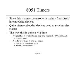
Time Delay Generation and Calculation • For the CPU to execute an instruction takes a certain number of clock cycles. • In the 8051 family, these clock cycles are referred to as machine cycles. • We can calculate a time delay using the available list of instructions and their machine cycles. • In the 8051, the length of the machine cycle depends on the frequency of the crystal oscillator connected to the 8051 system.
Time Delay Generation and Calculation (cont’d) • The frequency of the crystal connected to the 8051 family can vary from 4MHz to 30MHz. • In the 8051, one machine cycle lasts 12 oscillator periods. • Therefore, to calculate the machine cycle, we take 1/12 of the crystal frequency and then take the inverse.
Example • The following shows crystal frequency for three different 8051-based systems. Find the period of the machine cycle in each case. (a) 11.0592MHz (b) 16MHz (c) 20MHz
Solution • 1/11.0592MHz = period per oscillation Machine cycle = 12x = 1.085μs • 1/16MHz = period per oscillation Machine cycle = 12x = 0.75μs • 1/20MHz = period per oscillation Machine cycle = 12x = 0.6μs
Question • For an 8051 system of 11.0592MHz, find how long it takes to execute each of the following instructions: (a) MOV R3,#55 (b) DEC R3 (c) DJNZ R2,target (d) NOP (e) MUL AB
Solution (a) MOV R3,#55 1x1.085μs (b) DEC R3 1x1.085μs (c) DJNZ R2,target 2x1.085μs (d) NOP 1x1.085μs (e) MUL AB4x1.085μs