Download
1 / 17
170 likes | 251 Vues
Calculation of Internal Electrical Resistance and Power Loss in a Electrochemical Cell by fitting Polarization Curve Data to the Butler-Volmer Equation. Craig E. Nelson - Consultant Engineer. Basic Circuit Model. Simple Circuit Model For Basic Power Loss Analysis.

E N D
Calculation of Internal Electrical Resistance and Power Loss in a Electrochemical Cell by fitting Polarization Curve Data to the Butler-Volmer Equation Craig E. Nelson - Consultant Engineer
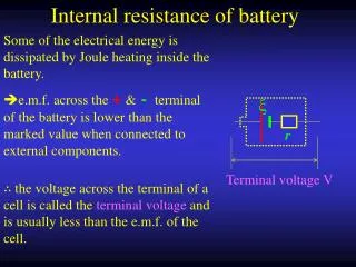
Simple Circuit Model For Basic Power Loss Analysis Rinternal = Vinternal / Icell Vinternal = Vopencircuit – Vload Therefore Rinternal = ( Vopencircuit – Vload ) / Icell Rinternal does not = - d(Vload) / d(Icell)
Cathode Crossover Current Source Anode Crossover Current Source Equivalent Circuit Model For a Cell Showing Anode and Cathode Crossover Loss Mechanisms
Cathode Conduction Loss Anode Simplified Equivalent AC Circuit Model for a Two Electrode Cell for General Interpretation of Impedance Spectroscopy Data and Current – Voltage Transient Performance Analysis
Log-Lin plot of a typical Measured and Fitted Cell V-I Curve
Simple Formulaic Model for a Generic Electro-Chemical Cell without Mass Transport Losses Vload = Vnernst - Vactivation - Vohmic Vload = Vnernst - Vtaffel * ASINH ( Iload / (2 * Io ) ) - Rohmic * Iload Vnernst = Thermodynamically reversible electro-chemical potential Vtaffel = slope of Taffel curve ASINH = Hyperbolic arc sine function Iload = Load current Io = thermodynamic exchange current in the absence of overpotential Rohmic = electronic resistance in current collectors + ionic resistance in electrolyte and Nafion layer
Helpful Correlation Formulae Fitted to Measured Data Vload = .9 - .095 * ASINH ( Iload / ( 2*.012 ) ) - .25 * Iload Vdrop_internal = .095 * ASINH ( Iload / ( 2*.012 ) ) + .25 * Iload Rload = [ .9 - .095 * ASINH ( Iload / ( 2*.012 ) ) - .25 * Iload ] / Iload Rinternal = [ .095 * ASINH ( Iload / ( 2*.012 ) ) + .25 * Iload ] / Iload Apparently the internal ionic and electronic resistance total is about .25 ohm
Linear scale plot of contributing parts of internal voltage drop vs. current
Log scale plot of contributing parts of internal voltage drop vs. current
Typical load and lost power and efficiency curves - log-linear scale
Breakdown of typical internal power loss & efficiency vs. current – linear scale
Breakdown of typical internal power loss & efficiency vs. current – log-linear scale
Conclusion • Incremental resistance ( - d(v) / d(i) ) should not be used • Simple circuit models based on the classic Butler-Volmer equations seem to model actual cell behavior quite well over two decades of output current • Use of the model equations allows a useful deconstruction of cell polarization curves. This, in turn, allows power loss from several principal mechanisms to be estimated with reasonable accuracy • Further work using electrical impedance spectroscopy methods can be used to refine the model presented here.