Download
1 / 42
430 likes | 436 Vues
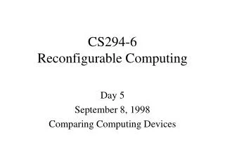
CprE / ComS 583 Reconfigurable Computing. Prof. Joseph Zambreno Department of Electrical and Computer Engineering Iowa State University Lecture #13 – FPGA Synthesis. Quick Points. Upcoming Deadlines Project proposals – Sunday, October 8 Not all groups accounted for

E N D
CprE / ComS 583Reconfigurable Computing Prof. Joseph Zambreno Department of Electrical and Computer Engineering Iowa State University Lecture #13 – FPGA Synthesis
Quick Points • Upcoming Deadlines • Project proposals – Sunday, October 8 • Not all groups accounted for • Midterm – Thursday, October 12 • Assigned next week Tuesday (following conceptual review in class) • Short, not a homework • HW #3 – Tuesday, October 17 CprE 583 – Reconfigurable Computing
Synthesis syn·the·sis (sin’thu-sis) n. – the combining of the constituent elements of separate material or abstract entities into a single or unified entity • For hardware, the “abstract entity” is a circuit description • “Unified entity” is a hardware implementation • Hardware compilation (but not really) CprE 583 – Reconfigurable Computing
FPGA Synthesis • The term “synthesis” has become overloaded in the FPGA world • Examples: • System synthesis • Behavioral / high-level / algorithmic synthesis • RT-level synthesis • Logic synthesis • Physical synthesis • Our usage: FPGA synthesis = behavioral synthesis + logic synthesis + physical synthesis CprE 583 – Reconfigurable Computing
Logic Synthesis • Input – Boolean description • Goal – to develop an optimized circuit representation based on the logic design • Boolean expressions are converted into a circuit representation (gates) • Takes into consideration speed/area/power requirements of the original design • For FPGA, need to map to LUTs instead of logic gates (technology mapping) CprE 583 – Reconfigurable Computing
Behavioral Synthesis • Inputs • Control and data flow graph (CDFG) • Cell library • Ex: fast adder, slow adder, multiplier, etc. • Speed/area/power characteristics • Constraints • Total speed/area/power • Output • Datapath and control to implement CprE 583 – Reconfigurable Computing
Outline • Quick Points • Introduction • FPGA Design Flow • Logic Synthesis • FPGA Technology Mapping • Behavioral Synthesis CprE 583 – Reconfigurable Computing
RTL . . C = A+B . Array Circuit A + C B FPGA Design Translation • CAD to translate circuit from text description to physical implementation well understood • Most current FPGA designers use register-transfer level specification (allocation and scheduling) • Same basic steps as ASIC design CprE 583 – Reconfigurable Computing
FPGA Circuit Compilation • Technology Mapping • Placement • Routing LUT LUT Assign a logical LUT to a physical location Select wire segments and switches for interconnection CprE 583 – Reconfigurable Computing
Standard FPGA Design Flow • Design Entry • Synthesis • Design abstracted as a list of operations and dependencies • Transformed into state diagrams and then logic networks (netlist) • Design Implementation • Translate – merges multiple design files into a single netlist • Map – groups logical components from netlist into IOBs and CLBs • Place & Route – place components on the FPGA and connect them • Device File Programming • Generates a bitstream containing CLB/IOB configuration and routing information to be directly loaded onto the FPGA CprE 583 – Reconfigurable Computing
FPGA Design Flow (Xilinx) Design Entry Functional Simulation HDL files, schematics Synthesis EDIF/XNF netlist Implementation NGD Xilinx primitives file Timing Simulation Device Programming FPGA bitstream CprE 583 – Reconfigurable Computing
Design Flow with Test Design and implement a simple unit permitting to speed up encryption with RC5-similar cipher with fixed key set on 8031 microcontroller. Unlike in the experiment 5, this time your unit has to be able to perform an encryption algorithm by itself, executing 32 rounds….. Specification Library IEEE; use ieee.std_logic_1164.all; use ieee.std_logic_unsigned.all; entity RC5_core is port( clock, reset, encr_decr: in std_logic; data_input: in std_logic_vector(31downto0); data_output: out std_logic_vector(31downto0); out_full: in std_logic; key_input: in std_logic_vector(31downto0); key_read: out std_logic; ); end RC5_core; VHDL description Functional simulation Synthesized Circuit Post-synthesis simulation CprE 583 – Reconfigurable Computing
Design Flow with Test (cont.) Synthesized Circuit Post-synthesis simulation Implementation Timing simulation Configuration On chip testing CprE 583 – Reconfigurable Computing
Synthesis Tools • Interpret RTL code • Produce synthesized circuit netlist in a standard EDIF format • Give preliminary performance estimates • Display circuit schematiccorresponding to EDIF netlist Performance Summary ******************* Worst slack in design: -0.924 Requested Estimated Requested Estimated Clock Clock Starting Clock Frequency Frequency Period Period Slack Type Group ------------------------------------------------------------------------------------------------------- exam1|clk 85.0 MHz 78.8 MHz 11.765 12.688 -0.924 inferred Inferred_clkgroup_0 System 85.0 MHz 86.4 MHz 11.765 11.572 0.193 system default_clkgroup =========================================================== CprE 583 – Reconfigurable Computing
Implementation Synthesis Circuit netlist Timing Constraints Constraint Editor Native Constraint File Electronic Design Interchange Format EDIF NCF UCF User Constraint File Implementation Native Generic Database file NGD CprE 583 – Reconfigurable Computing
LUT0 LUT4 LUT1 FF1 LUT5 LUT2 FF2 LUT3 Circuit Netlist and Mapping CprE 583 – Reconfigurable Computing
Placing and Routing FPGA Programmable Connections CprE 583 – Reconfigurable Computing
Place andRoute Report Timing Score: 0 Asterisk (*) preceding a constraint indicates it was not met. This may be due to a setup or hold violation. -------------------------------------------------------------------------------- Constraint | Requested | Actual | Logic | | | Levels -------------------------------------------------------------------------------- TS_clk = PERIOD TIMEGRP "clk" 11.765 ns | 11.765ns | 11.622ns | 13 HIGH 50% | | | -------------------------------------------------------------------------------- OFFSET = OUT 11.765 ns AFTER COMP "clk" | 11.765ns | 11.491ns | 1 -------------------------------------------------------------------------------- OFFSET = IN 11.765 ns BEFORE COMP "clk" | 11.765ns | 11.442ns | 2 -------------------------------------------------------------------------------- CprE 583 – Reconfigurable Computing
Configuration • Once a design is implemented, you must create a file that the FPGA can understand • This file is called a bit stream: a BIT file (.bit extension) • The BIT file can be downloaded directly to the FPGA, or can be converted into a PROM file which stores the programming information CprE 583 – Reconfigurable Computing
Logic Synthesis • Syntax-based translation • Translate HDL into logic directly (ab + ac) • Generally requires optimization • Macros • Pre-designed logic • Generally identified by language features • Hard macro: includes placement • Soft macro: no placement CprE 583 – Reconfigurable Computing
Logic Synthesis Phases • Technology-independentoptimizations • Works on Boolean expression equivalent • Estimates size based on number of literals • Uses factorization, resubstitution, minimization to optimize logic • Technology-independent phase uses simple delay models • Technology-dependentoptimizations • Maps Boolean expressions into a particular cell library • Mapping may take into account area, delay • Allows more accurate delay models • Transformation from technology-independent to technology-dependent is called library binding CprE 583 – Reconfigurable Computing
Boolean Network • A Boolean network is the main representation of the logic functions for technology independent optimizations • Each node can be represented as sum-of-products (or PoS) • Provides multi-level structure, but functions in the network need not correspond to logic gates primary outputs out1 = k2 + x2’ out2 = k3 + x1 k2 = x1’ x2 x4 + k1 k3 = k1 x4’ k1 = x2 + x3 primary inputs x1 x2 x3 x4 CprE 583 – Reconfigurable Computing
Terms • Support – set of variables used by a function • Transitive fanout – all the primary outputs and intermediate variables of a function • Transitive fanin – all the primary inputs and intermediate variables used by a function • Transitive fanin determines a cone of logic Cone primary inputs output CprE 583 – Reconfigurable Computing
Technology Independent Optimization • Simplification rewrites node to simplify its form • Network restructuring introduces new nodes for common factors, collapses several nodes into one new node • Delay restructuring changes factorization to reduce path length • Don’t know exact gate structure, but can estimate final network cost • Area estimated by number of literals (true or complement forms of variables) • Delay estimated by path length CprE 583 – Reconfigurable Computing
Don’t Cares in Boolean Networks • In two-level function, don’t-cares are defined at primary output • In Boolean network, structure of network itself introduces don’t-cares • Two types • Satisfiability – intermediate variable’s value is inconsistent with its function inputs • Observability – intermediate variable’s value doesn’t affect the network primary outputs f=yc a x y y == g a=b=0, f=1 can’t happen Don’t-care for f: y’g + yg’ b g=ab If a=1, then b is don’t-care a b c CprE 583 – Reconfigurable Computing
Factorization • Based on division: • Formulate candidate divisor; • Test how it divides into the function; • if g = f/c, we can use c as an intermediate function for f • Algebraic division: don’t take into account Boolean simplification • Less expensive then Boolean division CprE 583 – Reconfigurable Computing
LUT-based Logic Synthesis • Cost metric for static gates is literal • ax + bx’ has four literals, requires 8 transistors • Cost metric for FPGAs is logic element • All functions that fit in an LE have the same cost r = q + s’ s = d’ q = g’ + h d = a + b CprE 583 – Reconfigurable Computing
Behavioral Synthesis • Sequential operation is not the most abstract description of behavior • We can describe behavior without assigning operations to particular clock cycles • High-level synthesis (behavioral synthesis) transforms an unscheduled behavior into a register-transfer behavior CprE 583 – Reconfigurable Computing
Tasks in Behavioral Synthesis • Scheduling – determines clock cycle on which each operation will occur • Allocation – chooses which function units will execute which operations • Data dependencies describe relationships between operations: • x <= a + b; value of x depends on a, b • High-level synthesis must preserve data dependencies CprE 583 – Reconfigurable Computing
Data Flow Graphs • Data flow graph (DFG) models data dependencies • Does not require that operations be performed in a particular order • Models operations in a basic block of a functional model—no conditionals • Requires single-assignment form original code x <= a + b; y <= a * c; z <= x + d; x <= y - d; x <= x + c; single-assignment form x1 <= a + b; y <= a * c; z <= x1 + d; x2 <= y - d; x3 <= x2 + c; CprE 583 – Reconfigurable Computing
Data Flow Graphs (cont.) • Data flow forms directed acyclic graph (DAG): CprE 583 – Reconfigurable Computing
Binding Values to Registers • Registers fall on clock cycle boundaries CprE 583 – Reconfigurable Computing
Choosing Functional Units • Muxes allow for same unit used for different values at different times • Multiplexer controls which value has access to the unit CprE 583 – Reconfigurable Computing
Building the Sequencer Sequencer requires three states, even with no conditionals CprE 583 – Reconfigurable Computing
Class Exercise • How do the quadratic equation designs now compare? (total area usage including control) x A x A B B C + x x x + + C y y CprE 583 – Reconfigurable Computing
Choices During Behavioral Synthesis • Scheduling determines number of clock cycles required • Binding determines area, cycle time • Area tradeoffs must consider shared function units vs. multiplexers, control • Delay tradeoffs must consider cycle time vs. number of cycles CprE 583 – Reconfigurable Computing
Finding Schedules • Two simple schedules: • As-soon-as-possible (ASAP)schedule puts every operation as early in time as possible • As-late-as-possible (ALAP)schedule puts every operation as late in schedule as possible • Many schedules exist between ALAP and ASAP extremes CprE 583 – Reconfigurable Computing
ASAP and ALAP schedules ASAP ALAP CprE 583 – Reconfigurable Computing
Critical Path • Longest path through data flow determines minimum schedule length • Operator chaining: • May execute several operations in sequence in one cycle • Delay through function units may not be additive, such as through several adders CprE 583 – Reconfigurable Computing
Control Implementation • Clock cycles are also known as control steps • Longer schedule means more states in controller • Cost of controller may be hard to judge from casual inspection of state transition graph CprE 583 – Reconfigurable Computing
Controllers and Scheduling functional model: x <= a + b; y <= c + d; one state two states CprE 583 – Reconfigurable Computing
Summary • Synthesis is an overloaded term in the FPGA design world • Start from VHDL/Verilog/etc. or other system description • Generate bitstream, netlist, logic gates • Relevant steps: • Behavioral code to RTL code (.v) • RTL code to logic netlist (.edn) • Netlist to primitives file (.ngc) • Primitives file to implementation file (.bit) CprE 583 – Reconfigurable Computing