Download

1 / 18
180 likes | 277 Vues
SSC FORELINE THERMAL REACTOR Introduction and Specifications. www.SynSysCo.com. Contents. The Need for Foreline TRs TR Selection by Process Type HOT & COLD TR Pictures Data for SynSysCo MIT2500 HOT & COLD TR Application Methods Application Range Application Examples and Experience

E N D
SSC FORELINE THERMAL REACTOR Introduction and Specifications www.SynSysCo.com
Contents • The Need for Foreline TRs • TR Selection by Process Type • HOT & COLD TR Pictures • Data for SynSysCo MIT2500 HOT & COLD TR • Application Methods • Application Range • Application Examples and Experience • HOT & COLD TR Advantages • HOT TR Data • HOT TR Pictures • HOT TR Internal Construction • HOT TR Flow Diagram • HOT TR Features • HOT TR 3D Model
1. Reasons for Using a Foreline TR • Semiconductor and LCD Manufacturing is requiring larger wafers, larger chambers and higher gas flows. • High Gas Flows produce larger amounts of reactive by-products. • By-products cool and solidify on gas wetted surfaces in the pump body, pump housings, and rotors which shortens the life of the pump • Foreline TR Installation Yields Greatly Extended Pump Life and Significantly Increased MTBR • Foreline TRs are Specified and configured based on the Process Type being Supported and can be 1 of 3 types: • Hot/Cold configuration (Dual or Single Canister) • Hot Configuration • Cold Configuration
2. TR SELECTION 1) TI/TIN Applications are best supported by a HOT/ COLDDual TR Combination ◆ Reactive Formula: 200°C: TiCl4 + 2NH3 -> TiCl4·2NH3 (Powder Formation) • 200°C ~ 400°C : x(TiCl4·2NH3)+(8-2x)NH3+(6-X)TiCl4 -> 6TI + N2 + 24HCl(1<X<4) (TiN Barrier) • 400°C 이상 : 6TiCl4 + 8NH3 ↔ 6TiN + 24HCl (TiN Coating) 2) ALD Applications are best supported by a HOT/ COLDDual TR Combination ◆ Reactive Formula: AL(CH)3 + O3(+>400°C) -> AL2O3 + AL(CH3)2 + O2 + …………… 3) BW Applications are best supported by a HOT TR Configuration ◆ Reactive Formula: Si Reduction Step 2WF6 + 3SlH4(+>300°C) -> 4W(BW Barrier) + 3SiF4(Powder) + 6HF • Main Deposition Step WF6 + 3H2(+>300°C) -> W(BW Barrier) + 6HF 4) HT-SIN Applications are best supported by a COLD TR Configuration ◆ Reactive Formula: • SlH4 + N2O + NH3 + N2 (+>500°C) -> SIN(H) + Sl(NH2)4 + Sl(NH2)3 + ……………
3. HOT / COLD TR : SynSysCo -2500 HOT/ COLD Dual TR and Controller SSC-2500 Dual TR Controller
4. Data • Inlet Flange : MF 63 • Outlet Flange : MF 63 • TR Weight : 85kg • TR Volume : 50L • Material : SUS304 • TR Dimension (W mm × H mm) - Hot TR : Φ165.2 × 623 L - Cold TR : Φ165.2 × 618 L • Heater Temp : MAX 400°C • Control Box Dimension (W mm × D mm × H mm) : 250 × 300 × 130 • Power Supply : 220V × 2P • Power Consumption : MAX 4KW • Safeguard Shield External Temp MAX 40°C • Body Temp Inter lock Option : Temp Control ,Thermocouple, Out Switch
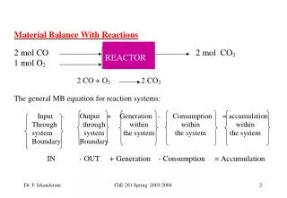
5. Application Method - Basis for use of HOT/ COLD TR for LPCVD Chambers Chamber Gas Reactions Release Energy and cause Wafer Deposition to occur However only about 30% of the gas reacts in the process Non-reacted gasses travel downstream toward the pump. The HOT/Cold TR configuration intercepts these gasses and 1st applies energy on the HOT side of the TR to complete the gas reactions. The resultant powder deposition is then collected on the COLD side of the TR and is prevented from depositing in the pump. This induced reaction, phase transition, and deposition has proven to be the most effective means of reducing by-product deposition in process pumps.
6. TR Installation Locations TR installed between 1st stage blower and rough pump. COLD TR HOT TR HOT/COLD TR Configuration SSC-2500 TR General Arrangement
8. HOT / COLD TR Advantages • The HOT Side uniformly heats gas via direct contact with an internal heated plate labyrinth • This energy reacts excess by-products with Al and then the Cold TR delivers a rapid temperature change and Al2O3 is captured in the Cold side • Large particles drop out and are captured via the dynamics of the TR flow design • Small particles are captured via a mesh filter • Hot side labyrinth plate temperature and surface area is determined by process gas flow rates • PID Control provides precise ±2°C control • O-Ring and Metal Seal Designs combine to handle the high temperatures and prevent leaks • The TR’s open structure is designed to not impact pumping speed • Hot TR external temperature shield has a maximum temperature of 40C • View Ports are installed to monitor powder build up in the TR.
HOT & COLD TR 3D Model HOT & COLD TR 3D Cross Section HOT & COLD TR 3D Model
9. HOT TR Data • Inlet Flange : MF 125 • Outlet Flange : MF 125 • TR Weight : 60 kg • TR Volume : 40 L • Material : SUS304 • TR Dimension (W mm × H mm) : Φ380 × 520 L • Heater Temp : MAX 300°C • Control Box Dimension WxDxH ( mm) 250 × 250 × 170 • Power Supply : 220V × single or three phase • Power Consumption : MAX 4KW
10. HOT TR Pictures SSC-2005 HOT TR SSC-2005 HOT TR Internal View
11. HOT TR Internal Arrangement MF 125 Inlet MF 125 Inlet CF Flange Heater Temp Controller MF 125 Outlet MF 125 Outlet
13. HOT TR Safety Management Features • The SSC-2500 enables precise setting of temperature to accommodate process gas flow rates, and produces uniform gas heating and known exhaust temperatures. • Leak Management and Monitoring with the SSC-2500 TR: • The Hot TR induces reaction of non-reacted gasses (Such as SiH4, WF6 and H2) and creates by-product powder. This reduces the potential for gasses to leak from the system and create a hazard. • Hot TR temperature is maintained at 240°C without gas flow. When process gasses flow into the TR, the temperature will fluctuate in a range. For example, ~210° to ~ 270°C. • Via testing of the system upon installation of the TR, a known range is determined for each process and registered in the controller. (For example 220C to 260C) • Consequently, if a leak occurs the established temperature range will be violated and the controller will alarm, initiating an inspection of the system.
FAB Monitoring and Management • TR integrate into Fab Monitoring/Control Networks • Remote TR Controller monitoring and control is available • Process Tool Touch Screen integration is available via auxiliary device software provided b y the tool manufacturer • TR Display Panels can provide status of critical parameters