Download
1 / 17
180 likes | 433 Vues
Machining: Family of Material Removal Processes. Material is removed from a starting work part to create a desired geometry. Material In. Removal of chips. Material Out. Machining Process. 1. Concept. - Any type of materials could be cut: ceramic ?.

E N D
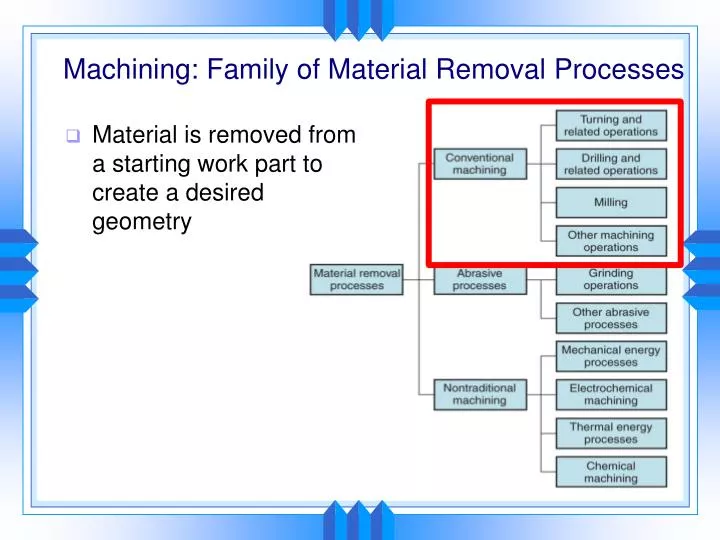
Machining: Family of Material Removal Processes • Material is removed from a starting work part to create a desired geometry
Material In Removal of chips Material Out Machining Process 1. Concept - Any type of materials could be cut: ceramic ? - There is a family of machining processes: abrasive, etc handout 9 machining process
Various types of machining processes Drilling Turning Peripheral milling Face milling handout 9 machining process
What function and quality level can machining processes achieve? - Dimension accuracy: 0.025 mm - Surface quality: 0.4 um - Any shape handout 9 machining process
What are generic features in any machining operations to make cutting processes work? - Two motions: tool motion and work motion - Primary speed and feed (rate) - Relative motion between the two motions generates mechanics to form chips and remove them handout 9 machining process
2. Cutting Tools Cutting Mechanisms handout 9 machining process
2. Cutting Tools Major cutting parameters Material Removal Rate MRR = (v)(f)(d) handout 9 machining process
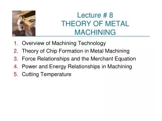
3. Engineering Analysis • Machine equipment to do material removal process: • theory of chip formation, energy, and power - Tool life: tool failure causes quality problem - Productivity - Quality assurance handout 9 machining process
tc to Ls 3.1 Theory of chip formation Orthogonal Cutting Model –converts 3d to 2d • Chip thickness ratio, r = to/tc(tc > to) • MRR = (v)(to)(w) handout 9 machining process
3.1 Theory of chip formation E- Efficiency that accounts for loss of the machine tool handout 9 machining process
3.2 Tool life • Fracture failure: force becomes excessive, causing sudden brittle fracture - Temperature failure: temperature is too high, causing the material at the tool point to soften - Gradual wear: (1) crater wear (2) flank wear handout 9 machining process
- The objective of selecting tools should ensure that only the gradual wear mode will occur - Tool design: materials and geometry - Except for tool design parameters (system parameters), tool life is a function of operating parameters (d) (f) (v) Cooling methods ( fluids) handout 9 machining process
3.3 Productivity Productivity is also called removal rate which is computed by the following equation: (d) (f) (v) 3.4 Quality System parameters Operating parameters Example: - Rough cutting (f: 0.4-1.25mm/rev; d=2.5-20mm) - Finish cutting (f: 0.125-0.4mm/rev; d=0.75-2.0mm) handout 9 machining process
Summary System parameters Operating parameters Tool (d) (f) (v) -> Power Material Cooling methods Goal: Select operating parameters to ensure no failure with the whole system and satisfactory quality handout 9 machining process
Design Considerations in Machining • Design parts that require little, and if possible, no machining • Use net shape or near net shape processes • Specify tolerances • Use tighter tolerances only where required • Specify surface finish • Use better surface finishes where required • Avoid machining sharp features (i.e. internal corners) where possible • Require sharp cutting tools that can break more easily • Avoid deep holes that must be bored • Difficult to maintain tool stiffness • Provide seats for drilling • Design part so standard cutting tools can access easily
Design Considerations in Machining • Design with materials that have good machinability • Design part features that used standard cutting tools • Avoid unusual hole sizes, threads, angles, and shapes requiring special form tools or special contouring • Design part with simpler geometries • Minimize or avoid angles and contours where possible • Design parts to have as few setups, one if possible • I.E. changing position of part and changing cutting tool
Design Considerations in Machining • Design machined part sizes that are close to standard available stock sizes • Less material to cut • Design machined parts to be rigid enough to withstand cutting forces and clamping • Avoid thin and narrow parts • Avoid undercutsas they require additional setups and special tooling