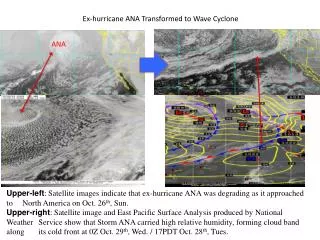
Download
1 / 82
820 likes | 969 Vues
The ANA Project. Kaiserslautern, Germany 4 March 2012. Disclaimer. ANA has been a collaborative effort – 10 partners Many thanks to all team members! But specifically for the core architects and developers: Christian Tschudin Christophe Jelger Ariane Keller Franck Legendre

E N D
The ANA Project Kaiserslautern, Germany 4 March 2012
Disclaimer ANA has been a collaborative effort – 10 partners Many thanks to all team members! But specifically for the core architects and developers: • Christian Tschudin • Christophe Jelger • Ariane Keller • Franck Legendre • Simon Heimlicher • Ghazi Bouabene
Networking Characteristics Private↔public Control↔data Delay tolerant↔real time Local↔global Resource constraint↔unlimited resources Reliable↔best effort
The Internet Hourglass Private↔public Control↔data Delay tolerant↔real time Local↔global Resource constraint↔unlimited resources Reliable↔best effort
Motivation • The Internet suffers from architectural stress: • not ready to integrate and manage the envisaged huge numbers of dynamically attached devices (wireless revolution, mobility, personal area networks, etc) • Lacks integrated monitoring and security mechanisms Consensus in the research community* that a next step beyond the Internet is needed. * as seen by the number of recent related projects and initiatives (FIRE, GENI, FIND, FP7, …)
Everythingon IP The Internet Hourglass Voice, Video, P2P, Email, youtube, …. Protocols – TCP, UDP, SCTP, ICMP,… Changing/updating the Internet core is difficult or impossible ! (e.g. Multicast, Mobile IP, QoS, …) Application layer Homogeneous networking abstraction IPv6 IPvX IP Disruptive approaches need a disruptive architecture Link layer IP on Everything Ethernet, WIFI (802.11), ATM, SONET/SDH, FrameRelay, modem, ADSL, Cable, Bluetooth…
Objectives • Goal: To demonstrate the feasibility of autonomic networking. • Identify fundamental autonomic networking principles. • Design and build an autonomic network architecture. • ANA in a blink: • Network must scale in size and in functionality. • Evolving network: variability at all levels of the architecture. • ANA = framework for function (re-)composition. • Dynamic adaptation and re-organization of network. • Networks have to work doing research through prototypes. • Early build an experimental network architecture. • Prototype used as feedback to refine architectural models. Architectures are not built, they grow!
Scenario – today • each device has to implement IP • IP address configuration through DHCP, zeroconf, ad hoc mode • routing protocol has to be agreed on • Most often results in manual configuration
ANA core ANA core ANA core ANA core ANA core ANA core ANA core Scenario – with ANA New ANA Compartment • Self-organization • determine comm. Protocol (non-IP) • form compartment • intra-compartment routing • service discovery • Self-association • Node bootstrapping • neighborhood discovery • address configuration • functional composition (suitable network stack) • Beyond IP!!! • Self-optimization • enhanced & integrated monitoring • functional re-composition • resilience
ANA core ANA core ANA core ANA core ANA core Scenario – with ANA Other ANA Compartment inter-compartment routing ANA Compartment Internet (IP Compartment)
Heterogeneity • We have to extend the waist and host more paradigms • Future networks have to scale in size AND functionality • Enable network evolution • Federation instead of homogeneous abstraction Application layer Generic framework Sensor Home NW Pub/Sub IP ??? Clean Slate Link layer We need a framework that is able to host multiple networks ANA framework
The ANA Project • To enable this vision we need: • The ANA core • Highly configurable network stack • Self-* properties • Service discovery • Self-organization • Self-optimization • Novel protocols • Functional composition
From Layers to Functional Composition • Per application port • UDP/TCP handling • IP does defragmentation, checksum,… • All packets from Ethernet with: 0x0800 IP0x86DD IPv60x809B Apple Talk App Layer Trans Layer Net Layer MAC Layer Phy Layer
From Layers to Functional Composition • At least same functionality as before, but decomposed • Allows for composition of functionality / services Also: • New functionality integrated in protocol stack • Not so novel, but we add • Dynamic re-configuration • Autonomic properties Applications Checksum Reliable Transport Routing Mobility Prediction Functional Compartment Monitoring Fragmentation Phy/MAC Layer
Functional Composition Application Layer passive monitoring adaptive monitoring Pub/Sub AODV TCP Service discovery OSPF UDP probing Mobility prediction SAFT RIP capture Service placement SCTP FBR system monitor DSR New TP? New RP? Virt. Coord New prot? Minimum Infrastructure Maximum Extensibility Dispatching Table ANA core Functionalcomposition IP frame OSI ATM frame IPX Phy/MAC Layer
ANA core ANA core ANA core ANA core ANA core ANA core ANA core ANA core ANA core ANA core ANA core ANA core Scenario – with ANA Extensible APIs and Transitioning Network Node End Node Functional Composition Applications Applications Monitoring Compartment 2 OneLab2 Routing and Transport Compartment 1 Compartment n ServiceDiscovery Internet Self-Association & Organization
Pitfalls in network architecture design Static/rigid standards instead of mechanisms for change management: • e.g. Global address space (requires uniqueness and global coordination) Leaking of and relying on network internal details: • e.g. Built-in address dependency (i.e. address-centric architecture vs address agnostic) To avoid running into such pitfalls, we adopt an incremental approach via prototyping cycles : • Helps revealing faults or inconsistencies in the architecture design, gain experience and acceptance
ANA: the common denominator ANA must permit variability at all levels of the architecture: • Multiple variants to perform a given task. • Different networks co-exist and compete. • The architecture is open for extensions and (evolution). And this should be done in an autonomic way (less humans in the control loop)
What did ANA do, finally?Socket De-Construction Semanticrichness Changing set ofNW funct. Socketinterface adaptionlayer ANA primitives Mappings to hardware,software systems t
You cannot "build" an architecture, you "grow" it • The project was articulated around 2 prototyping cycles. • Methodology: design, test/validate, refine. 2006 2007 2008 2009 2010 Design phase First "Blueprint" (architectural model) First prototyping phase 2nd prototyping phase Extra time Final integration Testing + feedback phase 2nd design phase Mature "Blueprint"
Example Scenario 1: Sensor Network • Distributed nodes to gain information about the environment • Fire alarm • Temperature measurement in permafrost • Limited resources (power, memory, CPU, etc.) • Network conditions can change frequently • Runtime customization of network stack to save power
Example Scenario 2: Video Surveillance System • Surveillance of train stations or airports • Communication between cameras • Communication from cameras to administrator • 100% uptime required • Integration of new features without service disruption • Software updates for bug fixes without service disruption
Flexible Protocol Graph – Multiple Nodes • Blocks loaded by an administrator • Protocol stack changes • Negotiation between different nodes • Maintenance: Use existing protocol graph for negotiation negotiation
Flexible Protocol Graph – Multiple Nodes • Blocks loaded by an administrator • Protocol stack changes • Negotiation between different nodes • Maintenance: Use existing protocol graph for negotiation negotiation
ANA Blueprint a look from inside
ANA: a meta-architecture • ANA does not impose how network compartments should work internally: the ANA framework specifies how networks interact. Sensor Home NW Internal operation is not imposed Pub/Sub IP … ANA specifies interfaces and interactions with network compartment leading to multiple and heterogeneous compartments but generic interaction ANA framework
A meta-architecture needs abstractions Abstractions permit to "hide" heterogeneity. • Functional Block (FB) • Information Dispatch Point (IDP) • Information Channel (IC) • Compartment. ANA contribution: extract the „basics“ of all computer communications, not only Internet specific concepts
Functional Blocks (FBs) Code and state that can process data packets. • Protocols and algorithms are represented as FBs. • Access to FBs is via “information dispatch points” (IDPs). • FBs can have multiple input and output IDPs. • FB internally selects output IDP(s) to which data is sent. FB FB data is sent to IDP which has state to call correct function inside FB
Information Channels (ICs) FBs do packet processing. We also need „packet transfer“. • “Information Channels“ are primitive, unidirectional datagram transport entities • ICs interlink functional blocks, but can also be put in series. • Data is sent to an IDP connected to an IC. • Note: „channels“ are an not tangible, usually distributed Various types of information channels:
ANA Compartment • Compartment (CT) = space where FBs, IDPs and ICs live • CTs, beside IDPs, probably the most important ANA contribution • Compartments indicate management borders, but alsoother grouping: name space, policies, technology, hardware etc • Observation: The Internet lacks compartments, at least officially
ANA – a Framework for Compartments • Compartment = wrapper for networks. • ANA does not impose how network compartments should work internally: the ANA framework specifies how networks interact. … ANA specifies interfaces and interactions with any network compartment Internal operation is not imposed leading to multiple and heterogeneous compartments but generic interaction ANA framework
Compartments and « Members » • Compartments offer connectivity among „compartment members“ • A (network) compartment defines how to join and leave a compartment: member registration, trust model, authentication, etc. • Each compartment defines a conceptual membership database. • Registration: explicit joining and exposing is required ("default-off" model).
Member resolution • Defines How to reach (communicate with) another member: peer resolution, addressing, routing, etc. • Resolution: explicit request before sending ("no sending in the void").
Compartments and Layers • Compartments can be overlaid, i.e. compartments can use the communication services of other compartments. • The compartment abstraction serves as the unit for the federation of networks into global-scale communication systems. • It defines interaction rules with the "external world", the compartment boundaries (administrative or technical), the peerings with other compartments, etc.
What about addresses and names ? Addressing and naming are left to compartments. • Each compartment is free to use any addressing, naming, and routing schemes (or is free to not use addresses, for example in sensor networks). The main advantages are: • No need to manage a unique global addressing scheme. • No need to impose a unique way to resolve names. • ANA is open to future addressing and naming schemes. The main drawbacks are: • Back to the CATENET challenges : How to inter-network in such heterogeneous address/name spaces ?
Local labels for handling (global) addresses • Target resolution returns a local label = IDP • IDPs are "indirection points inside the network stack". • Addresses/names = input for the resolution process. • The IDP then maintains the state to reach the destination.
Local labels for handling (global) addresses Why is this useful? ("startpoints instead of endpoints") • Ability to bind to destinations in an address agnostic way. • This is important to support many flavors of compartments that can use different types of addresses and names. • Useful decoupling between identifiers and means to address them. • Important to permit dynamic re-binding of communications. IC A data is sent to IDP which has state to reach the destination CTX = 10.1.2.3 SRV = tcp:80
How CTs, ICs, FBs, and IDPs fit together Node compartment Node compartment FB1 FB2 IC c a b Networkcompartment
Example of communication setup • Interaction with the node compartment is via a special kind of FB called an "access object (AO)". • For example, register and resolve requests are sent to the AO. client1 client2 ANA client has a control channel to the node compartment. This indicates that FB is the control-FB for the compartment p v Access object (FB) to private view of node compartment
Example of communication setup (2) • Clients get access to the network compartment access objects. client1 client2 Network Compartment Access objects (FB) to Network compartment e f p v Client has now access to the membership database of the node compartment which contains the list of available network compartments.
Client2 registers (via the IDP 'f') an identifier "B" with network compartment. Conceptually, this creates an entry in the membership database. Example of communication setup (3) In the compartment database there is now a member B. In the export view, this IDP indicates that client2 is reachable via some identifier (e.g. B). client1 client2 B = … b e f p v b "stack" FB
Example of communication setup (4) • Client1 resolves (via the IDP 'e') the identifier "B" and receives startpoint IDP 'a'. client1 client2 B = … a b f e p v b a "stack" FBs i s s i For a link-layer compartment, this IC abstracts the physical link.
Example of communication setup (5) • Typically, client1 only sees exported view (unless compartment exposes internal operation). client1 client2 Export view of the compartment a b