Download
1 / 29
330 likes | 530 Vues
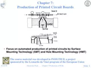
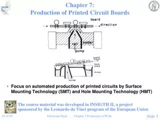
Laying out Interconnects on Optical Printed Circuit Boards. ANCS 2014. 20-21 October 2014. Apostolos Siokis , Kostas Christodoulopoulos, and Emmanouel (Manos) Varvarigos manos@ceid.upatras.gr University of Patras & CTI “ Diophantus ”, Greece. Overview.

E N D
Laying out Interconnects on Optical Printed Circuit Boards ANCS 2014 20-21 October 2014 ApostolosSiokis, Kostas Christodoulopoulos, and Emmanouel (Manos) Varvarigos manos@ceid.upatras.gr University of Patras & CTI “Diophantus”, Greece
Overview • Motivation/Optical Interconnects • Focus on-board (optical printed circuit board) level • Topology layouts • Methodology for designing on-OPCB interconnects • Application of methodology for a real HPC system
Motivation • Higher computation density (more cores per chip) higher capacity requirements • Copper wire limitations • High capacity only for short distance, Density issues • Increased power consumption • Optical interconnects at short distances: promising solution for replacing copper in future DC and HPC systems “Data Movement Not Flops, is the Bottleneck to Performance” Al Geist in Paving the Roadmap to Exascale, SciDAC Review 2010
Optical interconnects (evolution) • State of the art: • active optical cables (AOC) are the norm for rack-to-rack communication in DC and HPC • Target: board-to-board, on-board, and on-chip (distances < 20 mm) 2010 Optical waveguides on board- OPCB All-optical routers
On-OPCB level of System Hierarchy New photonic components • Architecture and topology design needs to be re-visited, re-addressed, and re-evaluated • Physical layer constraints determine the type of architectures feasible (e.g. mesh dimensionality) • Bottom-Up approach: • Study the particularities of each level of packaging hierarchy and move to higher levels • Focus on boards: Optical Printed Circuit Board (OPCB) • Topology lay-out for OPCBs determines: • number of modules put on-boards (thus required area) • number of bends, crossings, length (thus losses) • Need to search among feasible topologies and their lay-outs and select the best
Lay-out strategies for OPCBs Propose • A lay-out strategy for OPCBs • Direct networks (mesh, torus, fully connected topology families) • Each host is directly connected to a routing element • Routers connect to each other to form the topology • Most HPC systems are built with mesh-torus networks • A methodology for on-OPCB interconnects design (implemented in an Automatic Topology Design Tool) • Takes into account the proposed lay-out strategy, the physical layer specs, and the targeted performance • Calculates all feasible topologies and selects the optimum one
Classic electrical lay-out Models • Proposed approach: adapt lay-out strategies for electrical interconnects • Classic lay-out models for electrical interconnects: • Nodes laid-out in a 2D grid exhibiting only column- or row-wise communication simplify 2D design to that of 1D (collinear) lay-outs of a column and a row • Wires laid-out in tracks parallel to the collinear lay-out direction • 2 layers needed for non-planar topologies • At each layer no crossing is allowed • Vertical wires on layer 1, horizontal on layer 2, “vias” to connect the layers • Extensions to >2 layers (to reduce area) 2-D (3x4)logical lay-out of a 3x2x2 mesh Actual lay-out layer 1 (vertical wires) Actual lay-out Layer 2 (horizontal wires)
Electrical lay-outs examples 2-D (3x4)logical lay-out of a 3x2x2 mesh Collinear logical layout of 3-ary 2-cube Collinear logical layout of 9 fully connected network
OPCBs particularities • Links on OPCBs: single-mode or multi-mode waveguides • Waveguided communication (differences to electrical): • Bending radius required (cannot have 90o bends, nor vias) • Crossings possible at the same layer (at various crossing angles), but need to account for the induced losses and crosstalk • Propose a single layer lay-out strategy (second layer is allocated for the other direction of communication) • Lay-out nodes in a 2D grid, following the electrical lay-out ordering so as to exhibit only column- and row-wise links • Links are also laid out in tracks in a 2D grid in the same manner as in the logical electrical lay-out, but bends are not 90o and spacing between tracks can be non-homogeneous • bending radius ro, and crossing angle θ
OPCB lay-out and reserved space ro: bending radius, θ:crossing angle, nodes laid out in 2D grid exhibiting only row- and column-wise communication, links in tracks in 2D grid • At each node reserve space • above for row-wise comm. • to the left for column-wise comm. • below for off-board comm. • Tracks spacing: • first track parallel to the nodes lay-out directionplaced at ro • Space left between the following tracksS=(1-cosθ) .ro • Neglect the pitch between waveguides in a bundle (same source-destination) 2 orders of magnitude lower than roand S • For θ=90o : S = ro • Smaller roand θ: less required area, but higher losses (and crosstalk) Off-board Lay-out design rules on 2D grid for OPCBs
OPCB lay-out and reserved space ro: bending radius, θ:crossing angle, nodes laid out in 2D grid exhibiting only row- and column-wise communication, links in tracks in 2D grid Off-board Off-board 2D (3x4)3x2x2 mesh lay-out for OPCBs Lay-out design rules on 2D grid for OPCBs
Node construction and lay-out • Node = 1 router and 1 or more transceiver optochips in a star network • Optochips and router: arranged in 2-D grid • Intra-node bending radius ri, could be less than inter-node radius ro (since losses are less) • Space left and specific pin allocation is followed to avoid intra-node crossings and enable the router to exit the node from north and west • Tx (VCSEL) array pin allocations (similar for the Rx array on chip): • Router chips with peripheral pinout (waveguides exiting four sides of the router) Note: # nodes = # routers (since 1 router/node)
Waveguide Length Matching • Outermost link: longer than the innermost link • Most protocols for electrical PCBs: • Differential Signaling (DS): 2 differential pairs per 1 link. • less crosstalk, less electromagnetic interference (EMI) than single-ended signaling. • Need to be length matched • Serial link-to-serial link: looser length matching requirements • Optical PCBs: • Greater signal propagation speed • No differential signaling required (far less crosstalk, EMI) • No need for DS, but if need to perform length matching: • Tighter waveguide pitch • S-waveguide bends (very small bends much cheaper in losses than 90o bends):
Layout strategy & area • 2D (4x4) layout of 4x4 Torus • 4 optochips / router, 80 router channels: off-board, 10 channels: router-to-router connection • For baseline: 52mm x 52mm chips, ro=20mm, ri=10mm, θ=90o • “Unrealistic” • Best improvement in required area: smaller chip footprints • Smaller crossing angles do not improve node area (no crossings occur within nodes)
Available OPCBs lay-outs • Fully connected topology: collinear lay-outs (all nodes are placed along a line – can be viewed as a single row of a 2D grid lay-out) • Mesh & torus topologies: Collinear and 2D grid lay-outs • Loss and Area: • Loss: add the losses by the crossings, bends and length for the worst waveguide. Crossing and bending losses are modeled as a function of the bending radius and crossing angles. • Area: # of tracks required, weighted with the appropriate spacing between them (space is again a function of the bending radius and crossing angles) • Given the power budget and the area of the board we can define if a given topology following the proposed lay-out strategy is feasible or not
Methodology for OPCB design • Given: • Physical layer specs (chips footprints, pinouts, board size,… ) • Traffic demands: #waveguides for host-router • Power budget • Demanded performance (bisection width) • Generate the optimal topology (within certain families) for OPCB • Complex problem: • design space is vast since there are several free parameters (routers-chips placed on board, waveguides allocation for each type of communication, topology, bending radius, crossing angle, …) • Need to check the feasibility of the solutions • Develop an automatic topology design tool for OPCB topology optimization
Automatic topology lay-out tool 2 phases 1. Find all feasible designs (satisfying constraints) • Generate all possible topology designs • For different # of hosts connected to a router • For different # of routers on board, router-to-router topology, # of waveguides for router-router communication • For a given topology use analytical formulas to calculate throughput for uniform traffic (a traffic model suitable for “general purpose” topology design) • Check if the topology lay-out is feasible: area, loss, performance (for uniform traffic) 2. Select the optimal design among the feasible ones: • maximize # of hosts on board while using the lowest # of routers • Other optimization functions can be used (without repeating phase 1)
Illustrative results • Baseline scenario (Phox-trot specs) • 168 pinout router, 8 Gbps per waveguide, PVCSEL=4.7dBm, PDsens=-13dBm, Lcoupling= 3dBm, crossing angle=90o • 12 waveguides for optochip to router communication • 12 = assuming Intel Xeon Phi 3100 processor chips of 1 TFLOPs and communication-to-computation ratio 0.1 bps/FLOPs • Multi-mode (polymer) waveguides (50 x 50 μm, 850 VCSEL wavelength) • Board size: A4 • Off-board communication: waveguided or with vertical cabling • Bending radius: ro=20mm (for router-to-router), ri=10mm (optochips-to-router) • Uniform traffic pattern • Suitable for “general purpose” topology design
Graphs reading • Results are presented as graphs • x axis: po percentage of off-board traffic/host • y axis: number of hosts on OPCB • Points in graph: (Nnode, topology type, Wb) • Nnode : number of hosts (optochips)/router, thus per node, • Topology type: router-to-router topologies naming is “t” for torus, “m” for mesh, “f” for fully connected, followed by the dimensions of the specific router-router networks • Wb :waveguides (pairs) within a waveguide bundle for router-to-router communication e.g. (4, m 4x5, 22): 4 hosts/router (thus a node has 4 hosts), nodes are connected in a 4x5 torus network and there are 22 waveguides for node-to-node (router-to-router) communication we can deduce that there are 20 nodes-routers in total and 80 hosts, 168-4.22-4.12=32 waveguides are used for off-board communication/node, where 4.22 is the waveguides for router-to-router communication in the 2D mesh, and 4.12 is the waveguides for router-to-host communication
Illustrative results • Vertical cabling: no waveguides for off-board comm. and no board pinout constraint • poff:percentage of traffic destined off-board (related to system size) • 90o crossings, Board pinout: 96 • For poff≥ 0.5, board pinout constraints the number of optochips on-OPCB
Different Board Pinouts • poff=0.9 • 90o crossings, Board pinout: 48 (= State of the art), 96 (=Phoxtrot target) • larger board pinout (400) and the use of smaller chips would allow denser integration
Impact of fewer router pinouts • 90o crossings, Board pinout: 400, Board area: A2 • Less available router pinout leads to more hosts on-OPCB
Application of methodology for HPC • Redesign a Cray XK7 Blade using optical interconnects • For this case we keep the same topology on OPCB • Logical topology of Cray XK7 Blade:1x4x1 • Part of a 3D torus • Gemini router chip • Cray XK7 Blade • Gemini router chip
Resulting optical layout • O/E router with 168 optical channels, 8 Gbps per channel (instead of Gemini router) • 1 electrical layer + 2 layer optical layout with polymer waveguides (currently only 88 optical channels available with 2 layers) optochip • 2nd opticallayer: similar but for the other communication direction
Pin Reallocation • Keep the same on-OPCB topology but optimize it assuming Uniform Traffic • Determine pin allocations for CPU-to router and router-to-router connections, to achieve ideal throughput=100% of the injected bandwidth/compute node • Pin allocation optimized for a 4x12x8 system size (4 racks): • Required board pinout: 288 (144 Tx + 144 Rx) • In the general case:Exhaustive topology search and optimization using the Automatic Topology Design Tool
Conclusion • Interconnection networks of HPC systems and Datacenters • Optical interconnects are deployed in shorter and shorter distances • Optical interconnections: need to revisit several architectural issues • Bottom-up approach: focus on Optical Circuit Printed Boards (OPCB) • Outlined differences of optical to electrical layout models • Proposed a lay-out strategy for OPCBs • Adapt classical electrical lay-out strategies for torus, mesh, fully connected networks • Developed a automatic topology design tool • Takes into account the proposed lay-out strategies • Calculates all feasible designs • Feasible in terms of area, losses, performance (for uniform traffic) • Selects the optimal one
Future Work • Enrich physical layer models with more details (crosstalk, dispersion) • Examine the impact of different waveguide materials • Expansion of the methodology to include higher packaging layers (rack-to-rack and DC level) • Examination of buses and indirect topologies (such as fat-trees) • Extend topology layouts/architecture for WDM-enabled modules • Performance evaluation of our designs under realistic traffic patterns using event-driven simulations
Research funded by • Any Questions?