Download
1 / 20
220 likes | 416 Vues
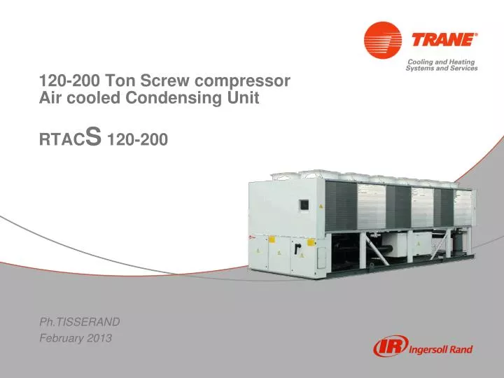
120-200 Ton Screw compressor Air cooled Condensing Unit. RTAC S 120-200 Ph.TISSERAND February 2013. Content. Range overview Unit component Options available DX design and Installation Unit control Performance selection. 2. Capacity coverage. at 400V/3/50Hz 8°CSST and 35°C Ambient.

E N D
120-200 Ton Screw compressor Air cooled Condensing Unit RTACS120-200 Ph.TISSERAND February 2013
Content • Range overview • Unit component • Options available • DX design and Installation • Unit control • Performance selection 2
Capacity coverage at400V/3/50Hz 8°CSST and 35°C Ambient Up to 52°C ambient 42°C ambient max 3
Capacitycoverage @4°C SST 52°C ambient @8°C SST 35°C ambient at 400V/3/50Hz • Range from 85 Ton to 205Ton at 50Hz • R134a Refrigerant • Compatible with 52°C ambient (HE and XE models) 4
Unit compressor mix High Efficiency Xtra Efficiency Legend Length(mm) X = fan Red = 4 rows coil Green = 3 rows coil N1 N1 Compressor N1 N1 size N1 N1 5
RTACS Unit component Fin and tube Cu/Al condenser Liquid filter Shut OFF valve Oil separator Oil cooler Service valve GP2 screw compressor • 2 circuits unit • 1 GP2 screw compressor per circuit • Liquid filter • Service valves • Oil separator • Fin and tube condenser coil • CH530 pressure and T° sensors 6
RTACS Options (standard product definition) • Unit efficiency • High Efficiency (HE) • Extra Efficiency (XE) • Condenser coil fin material • Standard Aluminum slit fins • Copper slit fins • Epoxy coated fins stock • Aluminum fins w/o slits • Condenser Fan • Standard • Low Noise (Not compatible with 52°C ambient) • 100Pa Available external static pressure • Control communication interface • BCI-C extensions (BACnet) • Tracer Comm3 • LCI-C Extensions • Refrigerant circuit accessories • With discharge service valves, without suction valves and without gauges • With discharge service valves, with suction valves and without gauges • With discharge service valves, without suction valves and with gauges • With discharge service valves, with suction valves and with gauges (Part of standard unit definition) • Unit finish • White paint over spray • Coil protection • Coil protection + white paint over spray 7
RTACS most popular optionAvailable under special (TFN) • IP54 rating • IP54 Control panel (Construction according to IP54 rules) • IP54 compressor terminal box (additional gasket) • IP54 condenser fans • 1000h Salt spray resistance compliance • Polyester powder paint on sheet metal part (2 sides) • Epoxy coated fins • Stainless steel frame bolts • Epoxy liquid layer on complete assembly • Polyurethane final RAL9002 complete layer on assembly • Control panel heater • Avoid any water condensation into control panel • Filter dryer • Filtering liquid cartridge replace by desiccant cartridge • Suction strainer is already integrated on compressor suction port • Solenoid valve (Field mounted) • 115V solenoid coil • Prevents liquid migration into evaporator • Extension bus cable for EXV and Temperature sensors • If sensors and EXV are far from each other in the AHU • Liquid sight glass • One sight glass is already included in the EXV. 8
Detail of Special1000h Salt spray corrosion proof treatment Standard treatment • Special treatment • RAL9002 Polyester powder paint on sheet metal part • Epoxy coated fins • Stainless steel frame bolts • Black epoxy liquid layer on complete assembly • Polyurethane final RAL9002 complete layer on assembly Polyurethane 40 µm thickness Epoxy 40 µm thickness Polyester 40 to 60µm thickness Sheetmetal part 9
RTACS installation CH530 LLID cable 4x1mm² copper wire shielded cable RTAC-S Condensing unit DX evaporator Air handler Unit Control panel 2 Liquid Solenoid Valves (Rating 110VAC) Airflow status (fan fail switch) (rating 110VAC – 1mA) Electronic Expansion valve Circuit #1 Circuit #2 Return Air Temperature sensor Leaving Air Temperature sensor LLID connectors
Key point for a successful DX system installation • Return oil to the compressors • Provide only liquid refrigerant at the expansion valves • Minimize capacity loss • Minimize the refrigerant charge • Shortest possible distances between components • Direct layout • Smallest possible line sizes (Shorter lines enhance reliability) • Simplicity 11
Refrigerant line arrangement Units at same level DX evaporator Air handler RTAC-S Condensing unit Suction line The piping between evaporator and RTACS shall not to exceed 61m (linear) feet or an equivalent length (includes equivalent length pressure drop fittings) of 91m. Liquid line DX evaporator Air handler RTACS below Evaporator Ideal arrangement Slope 0.4% Slope 0.4% RTAC-S Condensing unit Liquid line Slope 0.4% Suction line Impact on subcooling Good oil return 12
Refrigerant line arrangement Horizontal portions of the suction lines must be horizontal or downward sloping to the compressors. The pitch of the piping must be at least 13mm per 3m of run. Suction lines must be insulated. DX evaporator Air handler Slope 0.4% Slope 0.4% (1) RTACS above Evaporator RTAC-S Condensing unit Suction line Liquid line Max 15m (1) Note: If a suction riser is properly sized, oil will return to the compressor regardless of whether a trap is present. If a suction riser is oversized, adding a trap will not restore proper oil entrainment.
Evaporator selection • Check AHU evaporator coil selection : • RTACS is able to operate with only 1 electronic expansion valve per evaporator circuit. • Multiple coil in parallel is not recommended due to the risk of refrigerant mal distribution and poor evap efficiency. DX evaporator Coil #1 DX evaporator Coil #1 DX evaporator Coil #1 DX evaporator Coil #1 DX evaporator Coil #1 DX evaporator Coil #1 EXV#1 EXV#2 EXV#1 EXV#2 14
Sensor location Capacity of RTACS will be controlled according to supply air sensor. Supply air sensor should be placed into discharge plenum to reflect the most accurate air temperature in the discharge air duct DX evaporator Coil #1 DX evaporator Coil #1 Sampling tube can be used if discharge air plenum is not accessible Discharge air Temperature sensor 15
RTACS Control • RTACS is using the same logic as the chiller CH530 control algorithm: • Customer set point is Leaving Air Temperature • Compressor slide valve is move to adapt RTACS capacity to the leaving air temperature • Minimum capacity per circuit is 30%. All RTACS 120-200 are dual circuit unit, this means unit capacity modulation is linear from 100% to 15% (if nominal capacity selection is not in adaptive control mode). • All communication interfaces available has not changed for RTACS (BACnet, Comm3, Lon). • Leaving water temperature point has to be interpreted as Leaving Air Temperature • Entering water temperature point has to be interpreted as Return Air Temperature • There is no possibility to control directly the capacity of the unit (compared to RAUL). Customer set point can be offset to achieve equivalent function. 16
RTACS Commissioning • RTACS CH530 is controlling EXV opening to maintain compressor suction superheat. Special CH530 software has to be loaded in the unit using Techview. • Compressor suction superheat set point is adjustable via Techview. • Return and Leaving air sensor as well as EXV#1 and EXV#2 has to bounded at unit commissioning. • CH530 Flow switch digital input has to be connected to Fan fail pressure switch and fan contactor status. • Solenoid valves has to be connected to external contact of compressor. 17
How to quote, how to order? • RTACS is available only through ERTAC Epinal source. • Describe the need to sales support indicating • Design conditions : • Saturated Suction Temperature at design conditions (SST) • Minimum and Maximum Outdoor ambient temperature • Voltage including tolerance • Options affecting capacity : Condenser coil type. Fan type. • Evaporator Capacity (assuming 5K superheat). • Special option requested • Define TFN following Sales support answer • Enter order using ERTAC product mentioning TFN number. 18
What is supplied with Basic RTACS Basic RTACS unit is assuming the standard RTAC options configured with Spectrum… (-) Evaporator and liquid level control (-) Water piping (-) R134a refrigerant charge (+) N2 charge (+) Suction and liquid piping at the end of the unit (+) shut Off valves : Ball valve for liquid pipe, Butterfly valve for suction pipes. (+) 2 EXVs, 2 temperature Sensor (delivered spared in control panel) 19