Download
1 / 22
240 likes | 261 Vues
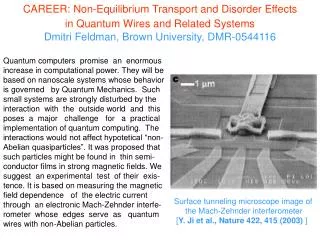
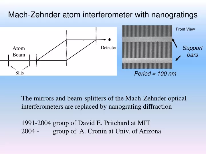
Mach-Zehnder atom interferometer with nanogratings. Front View. Support bars. Period = 100 nm. The mirrors and beam-splitters of the Mach-Zehnder optical interferometers are replaced by nanograting diffraction 1991-2004 group of David E. Pritchard at MIT

E N D
Mach-Zehnder atom interferometer with nanogratings Front View Support bars Period = 100 nm The mirrors and beam-splitters of the Mach-Zehnder optical interferometers are replaced by nanograting diffraction 1991-2004 group of David E. Pritchard at MIT 2004 - group of A. Cronin at Univ. of Arizona
I=I0[1+V sin(+ interaction)] V= 42 %, I0=190 kc/s PhD Perreault (2005) • This interferometer has been applied to measure: • polarisability of Na • decoherence effects • refraction index of gases for sodium waves • atom – surface van der Waals interaction • ….
collimated atomic beam exit 2 detector exit 1 3 laser standing waves Atomic interferometer with Bragg phase gratings L L= 0.6 m Beam separation: 100 µm The mirrors and beam-splitters of the Mach-Zehnder optical interferometers are replaced by Bragg diffraction on laser standing waves In the Bragg regime, diffraction of order p>1 can be used.
Atom interference fringes with 7Li diffraction order p = 1 counting time = 0.1 s/point fringe visibility V = 84 % mean output flux I0 = 24 k c/s This interferometer has been applied to measure - electric polarisability of 7Li - refraction index of gases for lithium waves - atom – surface van der Waals interaction
Mesure de l’interaction de Van der Waals window A: both beams pass through the grating B: one beam pass the grating C: both beams pass through the window
A, E: both beams pass through the grating B, D: one beam passes through the grating C: both beams pass through the window
Vary the atom velocity (750 – 3500 m/s) • Interpretation not simple: • for high atom velocities, the atom contributing • to the fringes probes smaller atom- surface • distances • The connection of the phase shift to C3 • depends on grating dimensions • (analysis under progress)
Atomic interferometer as a gyrometer/accelerometer • T: time of flight between 2 laser beams • kG: grating vector • a: acceleration or Coriolis term 2Wv • f= p kGa T2 • fSagnac = 2 p kGWv T2 • facceleration= p kG a|| T2 (kG≈4p/lres) lres is the first resonance line: No dependence on the atomic mass dependence on the atoms only through lres
Spatial/temporal interferometers • f= p kGaW|| v T2 Spatial interferometers: vT= L (Kasevich, Rasel, ) fL2/v Temporal interferometers: (Landragin, Rasel, …) fv • In both cases, similar dispersion of the • phase with atom velocity
Sensitivity to acceleration acc p kG a T2 a = = rot p kGW v T2W v The use of very slow atoms enhances dramatically the sensitivity to accelerations double interferometer with counterpropagating atoms cancellation of the acceleration phase
|e> h0 hL |g> Raman versus Bragg diffraction |k + 2kL, g> kL |k, g> |k, g> kL |k, g1> |k + k1 + k2, g2> |k, g> |k + 2kL, g> Coupling depends on laser power, detuning … p/2 and p pulses
Bragg |e> p=2 or larger hL h0 Siu Au Lee’s group and our group: p=3 and H. Mueller et al p=1,..,12 (Phys. Rev. Lett. 100, 180405, 2008) f= pkGa T2 |g> |k + 4kL, g> kL Raman kL p>1 not directly possible without changing the frequency of the lasers or applying additional pulses kL |k, g> kL
Bragg diffraction based atom interferometer as inertial sensor:State of the art: The existing interferometers (thermal atoms) with separated beams were not planned for inertial measurements : Pritchard/Cronin interferometer (Na, material gratings) Toulouse interferometer (Li, Bragg laser diffraction) Sensitivity (v= 1000 m/s):
What can we do ? (1) Slow down the atoms: for v= 10 m/s and L=0.6 m h= 1.7 cm Under construction standing waves h (2) Increase the atomic flux: x10 (x100 hopefully) (laser cooling, …) (planned) Fmin ≈ 0.4 mrad / Hz Rotation: f/p = 1.3 106 W s Acceleration: f/p = 6.7 104arad s2 m-1 Fmin ≈ 0.4 mrad / Hz p dW 3.1 10-10 s-1 Hz-0.5 p da 6.0 10-9 m s-2 Hz-0.5 Be aware of seismic noise ! interferometer stabilisation needed !
Interferometer suspension under progress Suspension by 3 wiresunder vacuum M3 M2 M1 Li D.B Newell et al Rev.Sci.Intr. 68, 3211 (1997) Horizontal isolation performance First measurements withourpendulum
Conclusion High precision measurement of the phase induced by atom-surface van der Waals interaction We are building: • a new Mach-Zehnder interferometer with a slow and intense beam of lithium, • suspension of the interferometer with servo loops to strongly reduce the seismic noise Interferometers with separated arms (Bragg diffraction) are interesting for inertial measurements How far can we go ?
Nanograting interferometer AtomicInterferences C= 41.6 %, I0= 186 kc/s (PhDPerreault)
Bragg Raman |e> |e> h1 hL h0 h0 p=2 p=2 ? • f= pkGa T2 ? |g> |g2> |g1> |k + 4kL, g> kL kL kL |k, g> kL
H. Mueller et al (Phys. Rev. Lett. 100, 180405, 2008)
Mesure de l’interaction de Van der Waals window A: both beams pass through the grating B: one beam pass the grating C: both beams pass through the window