Download
1 / 17
170 likes | 509 Vues
Implementation of Basic Digital Filter Structures. R.C. Maher ECEN4002/5002 DSP Laboratory Spring 2003. Digital Filters. DSP ALUs designed to do fast MACs Use Harvard architecture: place filter state in X memory, filter coefficients in Y memory

E N D
Implementation of BasicDigital Filter Structures R.C. Maher ECEN4002/5002 DSP Laboratory Spring 2003
Digital Filters • DSP ALUs designed to do fast MACs • Use Harvard architecture: place filter state in X memory, filter coefficients in Y memory • Try to avoid truncation until after all MACs Filter Implementation R. C. Maher
+ x[n] y[n] h0 Z-1 x[n-1] h1 Z-1 x[n-2] h2 Z-1 x[n-3] h3 FIR Filter Review Filter Implementation R. C. Maher
X Memory Y Memory Modulo N Buffer Memory Filter state (delay line) Modulo N Buffer Memory Coefficients (delay line) FIR Setup Input Accumulator Output Filter Implementation R. C. Maher
FIR Code for 56300 • Filter order ‘n’ • Input and Output in accumulator ‘a’ • r0: samples, r4: coefs, m0 & m4: n-1 move a,x(r0) clr a x:(r0)+,x0 y:(r4)+,y0 rep #n-1 mac x0,y0,a x:(r0)+,x0 y:(r4)+,y0 macr x0,y0,a (r0)- Filter Implementation R. C. Maher
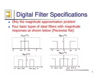
IIR Filters • IIR (infinite impulse response) filters allow zeros and poles; FIR allow zeros only. IIR can be more selective for a given filter order • IIR also called recursive filters: output depends on past inputs and past outputs • IIR designs are not guaranteed to be stable • IIR filters can be particularly sensitive to coefficient quantization Filter Implementation R. C. Maher
IIR Issues: Stability and Sensitivity • Finite precision of coefficients can lead to several issues: • In order to be unconditionally stable and causal, all system poles must be inside the unit circle (|z|<1). Coefficient roundoff may inadvertently move a pole outside unit circle • Finite coefficient precision “quantizes” pole locations: may change frequency response from ideal case even if still stable Filter Implementation R. C. Maher
Overflow Issues • Gain from input to storage nodes in the filter may exceed unity. This can cause filter state to be saturated (clipped), resulting in distortion • Typically must scale down (attenuate) the input signal, then scale up (amplify) by an equal amount on the output Filter Implementation R. C. Maher
Second-Order Sections • High-order filter polynomials involve terms that are products and sums involving many poles and zeros. Small roundoff errors when implementing filter can lead to large response errors • As with analog filters, it is typical to reduce sensitivity by using second-order sections Filter Implementation R. C. Maher
Implementing 2nd Order Sections • 2nd Order (bi-quad) expression • Numerator implements 2 zeros, denominator implements 2 poles (real or complex conj.) Filter Implementation R. C. Maher
+ Direct Form Bi-Quad y[n] x[n] b0 Z-1 Z-1 y[n-1] x[n-1] -a1 Z-1 b1 Z-1 x[n-2] y[n-2] b2 -a2 Filter Implementation R. C. Maher
IIR Code for 56300 • Direct Form II, with equations: w(n)=x(n)-ai1w(n-1)-ai2w(n-2) y(n)=w(n)+bi1w(n-1)+bi2w(n-2) • Since ai1 and bi1 may be > 1, need to divide all coefs by 2, then use special scaling mode for 2 on read from accumulator: ori #$08,MR sets “scale up”: 1-bit left shift on acc read Filter Implementation R. C. Maher
IIR for 56300 (cont.) • N = number of second-order sections • Filter state (w) in X memory: r0 • Filter coefs (a,b) in Y memory: r4 • Coefs stored in order: • a12/2, a11/2, b12/2, b11/2, a22/2, … bN2/2 • State (data) stored in order: • w1(n-2), w1(n-1), w2(n-2), w2(n-1), … wN(n-1) • m0 = 2*N-1, m4 = 4*N-1 • Initial gain in y1, input in y0, output in ‘a’ Filter Implementation R. C. Maher
IIR for 56300 (cont.) mpy y0,y1,a x:(r0)+,x0 y:(r4)+,y0 do #N,end_cell mac -x0,y0,a x:(r0)-,x1 y:(r4)+,y0 macr -x1,y0,a x1,x:(r0)+ y:(r4)+,y0 mac x0,y0,a a,x:(r0)+ y:(r4)+,y0 mac x1,y0,a x:(r0)+,x0 y:(r4)+,y0 end_cell rnd a Filter Implementation R. C. Maher
Other Filter Structures • Direct Form I and Direct Form II • Cascade and Parallel Realizations • Transpose Forms • Lattice Forms Filter Implementation R. C. Maher
EVM Note: External Memory • To use external memory on EVM, need to program the bus control register and the address attribute register 0 (see 56300 Family Manual) movep #$040821,x:M_AAR0 ;Compare 8 most significant bits ;Look for a match with address ;Y:0000 0100 xxxx xxxx xxxx xxxx ;No pack, no mux, Y enabled ;P and X disabled ;AAR0 pin active low movep #$012421,x:M_BCR ;One ext. wait state • Access to external memory is slower than internal memory: wait state stalls processor Filter Implementation R. C. Maher
Conclusion • DSP chips (including the DSP563xx) are designed specifically for fast digital filter implementations • Care must be taken to ensure that the practical details are addressed: • Coefficient quantization • Overflow and scaling • Computational complexity Filter Implementation R. C. Maher