Download
1 / 38
400 likes | 790 Vues
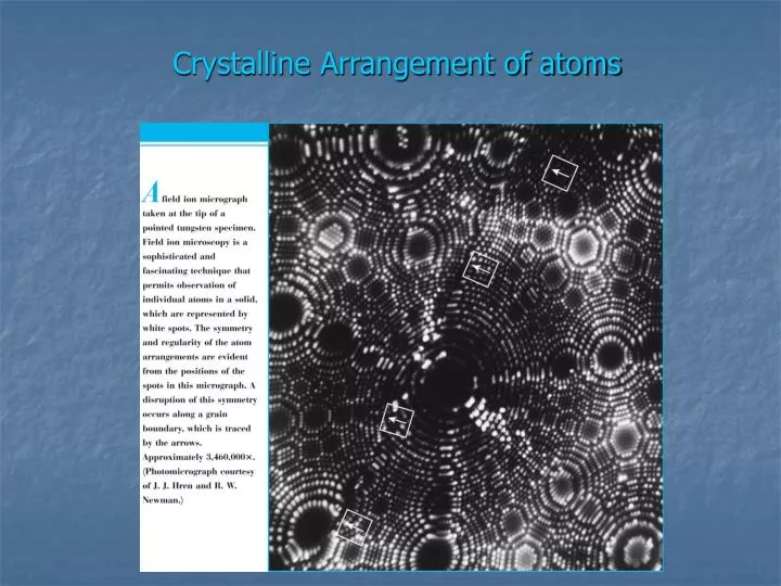
Crystalline Arrangement of atoms. Chapter 4 IMPERFECTIONS IN SOLIDS. The atomic arrangements in a crystalline lattice is almost always not perfect . There are defects in the way atoms are arranged in the crystalline solids.

E N D
Chapter 4IMPERFECTIONS IN SOLIDS • The atomic arrangements in a crystalline lattice is almost always not perfect. • There are defects in the way atoms are arranged in the crystalline solids. • So we can say that in crystalline solids some Lattice Irregularities are always present. • These crystalline defects are not bad. Some are intentionally introduced to improve the material.
Types of Crystalline Defects • POINT DEFECTS are classified on the basis of their geometry and dimensionallity. • POINT DEFECTS (Vacancies, self interstitials, impurity atoms) • LINE DEFECTS (one dimensional)(Dislocations) • INTERFACIAL DEFECTS (two dimensional)(Grain Boundaries)
Vacancies • Vacancies are always present in the crystalline solids. • Vacancies are created during process of solidification or due to thermal agitations of lattice atoms. • At a given temperature there is always present an EQUILIBRIUM CONCENTRATION of VACANCIES.
Activation energy Equilibrium No. of vacancies æ ö - N Q ç ÷ = v v ç ÷ exp è ø N k T No. of atomic Temperature sites. Boltzmann's constant -23 (1.38 x 10 J/atom K) -5 (8.62 x 10 eV/at om K) Each lattice site is a potential vacancy site EQUILIBRIUM CONCENTRATION OFVACANCIES • Equilibrium concentration of vacancies increase with temperature!
æ ö - N Q ç ÷ = v v ç ÷ exp è ø N k T slope N N v v 1 ln N N - Q /k v exponential dependence! T 1/ T defect concentration MEASURING ACTIVATION ENERGY • We can get Q from an experiment. • Measure this... • Replot it... 5
0.9eV/atom æ ö - N Q ç ÷ v v = ç ÷ exp -4 = 2.7 · 10 è ø N k T 1273K -5 8.62 x 10 eV/atom-K N A 3 28 3 r x 1m = 8.0 x 10 sites x For 1m , N = A Cu -4 28 25 N = (2.7 · 10 ) (8.0 x 10 ) = 2.2x 10 vacancies v ESTIMATING VACANCY CONC. 3 • Find the equil. # of vacancies in 1 m of Cu at 1000 oC. • Given: • Answer: 6
Impurities in Solids • Pure metal containing only one type of atoms Not Possible • Impurity atoms are always present. • These atoms exists as point defects. • In alloys, impurity atoms (alloying element atoms) are intentionally added. • An alloy is usually a solid solution of two or more types of atoms. • e.g. Fe + C Steel SOLVENT SOLID SOLUTION SOLUTE
TYPES OF SOLID SOLUTIONS SOLID SOLUTION SUBSTITUTIONAL SOLID SOLUTION Solute atoms replace (substitute) the solvent atoms in the solvent lattice INTERSTITIAL SOLID SOLUTION Solute atoms occupy the interstitial sites of the solvent lattice
Conditions For Substitutionl Solid Solubility • Four Conditionsmust be satisfied for obtaining appreciable (large) solubility of the substitutional solute in a given solvent lattice. • Atomic Size Factor:The atomic size difference between the solute and solvent atoms must be less than 15%. • Crystal Structure:Crystal structure of both solute and solvent must be same. • Electronegative:The electro negativity difference must be small. If this difference is large ionic compound will form instead of solid solution. • Valence:Higher valance metals will dissolve easily than low valance metals.
Ni + Cu Will they have large Solid Solubility? Check! 4 conditions NiCu Atomic Size 0.125 nm 0.128 nm Crystal structure FCC FCC Electronegativity 1.8 1.9 Valence +2 +1 Answer: Yes they will
HOW about CU + Zn ZnCu Atomic Size 0.133 nm 0.128 nm Crystal structure HCP FCC Electronegativity 1.6 1.9 Valence +2 +1 Answer: No they won’t
SPECIFICATION OF COMPOSITION • Two most common ways to specify the composition or concentration are • Weight or mass percent: weight of a particular element relative to the total alloy weight. • Atom percent: number of moles of an element in relation to the total moles of the elements in the alloy. • Weight %: where m1 and m2 represent the weight or mass of elements. • Atom %: where No. of moles (nm) = {(mass in grams) / Atomic weight
SPECIFICATION OF COMPOSITION (Contd.) • COMPOSITION CONVERSIONS • Weight% to Atom% • Atom% to Weight%
SPECIFICATION OF COMPOSITION (Contd.) • Weight% to Kg/m3 ( mass of one component per unit volume of material)
Example 4.2 • Derive Equation 4.6a • Solution: • Total alloy mass, Atom % of element 1, Simplifies to
DISLOCATIONS • Dislocations are LINEAR DEFECT and represent a line around which atoms in the crystalline lattice are misaligned. • Two Types of Dislocations • EDGE DISLOCATION • SCREW DISLOCATION • Also MIXED DISLOCATION
EDGE DISLOCATIONRepresented by a half atomic plane the edge of which ends within the crystal
BURGERS VECTOR • Burgers Vector b represents the magnitude and direction of lattice distortion created by the dislocation. • FOR EDGE DISLOCATION b is perpendicular to dislocation line. • FOR SCREW DISLOCATIONb is parallel to dislocation line.
BURGERS VECTOR • FOR METALLIC MATERIALS • The BURGERS VECTOR for a dislocation lies along a closed packed direction. • The Magnitude of the BURGERS VECTOR is equal to the interatomic or interpalnar spacing.
4.5 Interfacial Defects • Interfacial defects are boundaries that have two dimensions and normally separate regions of the materials that have different crystal structures and/or crystallographic orientations. • These imperfections include external surfaces, grain boundaries, twin boundaries, stacking faults, and phase boundaries. • EXTERNAL SURFACES • One of the most obvious imperfection boundaries is the external surface • The crystal structure terminates • Surface atoms are not bonded to the maximum number of nearest neighbors higher energy state than interior atoms. • To reduce this energy, if possible materials tend to minimize surface area not possible for solids.
INTERFACIAL DEFECTS(GRAIN BOUNDARIES) • Boundary separating two small grains or crystals having different crystallographic orientations in polycrystalline materials. • Within the boundary region, which is probably just several atom distances wide, there is some atomic mismatch in a transition from the crystalline orientation of one grain to that of an adjacent one. • Various degrees of crystallographic misalignment between adjacent grains are possible ( Figure 4.7).
4.5 Interfacial Defects (Contd.) • Tilt boundary • One simple small-angle grain boundary • Figure demonstrates how a tilt boundary having an angle of misorientation q results from an alignment of edge dislocations. • Twist boundary • When the angle of misorientation is parallel to the boundary • Due to an array of screw dislocations
The atoms are bonded less regularly along a grain boundary interfacial or grain boundary energy similar to surface energy. • Grain boundaries are more chemically reactive than the grains themselves as a consequence of this boundary energy. • Impurity atoms often preferentially segregate along these boundaries because of their higher energy state. • Because of less total boundary area, the total interfacial energy is lower in large or coarse-grained materials than in fine-grained ones. • Grains grow at elevated energy to reduce the total boundary energy