Download

1 / 35
350 likes | 537 Vues
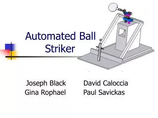
Striker. Autonomous Air-Hockey Gaming Experience. Group 8: Brian Thomas, EE Efrain Cruz, EE Loubens Decamp, EE Luis Narvaez, EE. Project Description. Autonomous robotic air hockey opponent: Puck-return Visual Effects Visual Tracking End-effector Dedicated regulated power supply.

E N D
Striker Autonomous Air-Hockey Gaming Experience Group 8: Brian Thomas, EE Efrain Cruz, EE Loubens Decamp, EE Luis Narvaez, EE
Project Description • Autonomous robotic air hockey opponent: • Puck-return • Visual Effects • Visual Tracking • End-effector • Dedicated regulated power supply
Motivation and Purpose Desire to gain experience with: • Computer vision • Autonomous robotics • Motion control • Software proficiency • Hardware design • PCB Design
Goals and Objectives • Autonomous robotic arm • ‘Real time’ game play • Desire of a “puck-return” system • Visual object tracking • Accurate trajectory predictions • Design our own power supply • Visual lighting effects • Convenient and user friendly environment
Microcontrollers Our choice of microcontroller was based on these basic criteria: • Microcontroller should have descriptive reference documentation available • Simple development environment • Processing frequency higher than 8 MHz • Digital, Analog and PWM pins available • Low voltage ( operating voltage 3-5V ) • Affordable (<$10.00) • Should have the necessary communication protocols – UART & SPI • Must have ability to control Striker arm.
Microcontroller Decision The Atmega328P met our requirements: • Testing can be easily implemented using Arduino Uno and Sketch IDE • Open source and abundance of support • Atmel offers free samples • Communicates through UART, SPI & I2C • High frequency (up to 20MHz with external clock) • Contains Analog, PWM & digital IO
Robot Arm Design based on the following criteria: • Hand crafted • Prismatic motion • Dedicated Microprocessor • Linear set-points no more than 2” apart • Must intercept puck’s motion towards goal • End-effector to have Propulsion with stroke no less than 1/4” • Needs to cover entire width of playing area
Prismatic Design • Driven by 2-phase bipolar Stepper Motor • Motion achieved by timing belt/pulley system • Built using T-Slots aluminum extrusions • End-effector gondola weight of 4.2 lbs
End-Effector • Pull type solenoid allows for propulsion of puck • Aligned so propulsion is parallel to side walls of playing surface • IRF620 allows for logic control of solenoid through TTL from Atmega328P
Motor Selection STP-42DB3018
Motor Driver: L298N • Dual full H-Bridge allows for control of bidirectional • Stepper Motor • Clamping diodes, 1N5822 used to protect against • voltage spikes from ‘back EMI.’ Features: • Bi-directional motor control for steppers and solenoids • Supply voltage range for motor: 2.5 - 46V DC • Peak output current for DC operation: 2.5A • Logic supply: 4.5 – 7V DC
Stepper Motor Control • Stepper Motor is Permanent Magnet motor that requires pulsed signals to move rotor. • Timing sequence is Full-step to achieve maximum Torque. Full Step Timing Sequence from PCB
Tracking System Raspberry Pi Raspberry Pi Camera Module
LED Lighting Objective • Fully Addressable • Have many color variations • Adds visual appeal to the gaming experience
LED Selection • LPD8806 programmable LED • 3 channels • 7 bits per channel resulting in 2,097,152 color options • Programmed using a derivation of C language called Wired • Controlled with PWM at a frequency of 1.2 MHz via an Atmega 328
Puck Return • Return puck on demand via toggle push button • Puck must be returned to player in less than 20 seconds • Powered by separate 24V, 72W power supply
Puck Return Conveyor System Calculations based on data collected: • Table total length is 82 inches • 1”= 0.0254m (U.S.I) • 82”= 2.0828m • t=16s • V = d/t → V = .13m/s or 5.125in/s • Conveyor system goes underneath of the table
Power Supply Uses wall receptacle to power up the air hockey table (120V AC, 60 Hz) Power supply is divided in two parts: • 24V @3A adjustable use to power up the Motors • Linear Regulated Power supply (LRPS) to supply our Electronic sub-systems. The LRPS provides 12V for our Solenoid, 5V for LEDs and Logic.
Power Supply – Motor & System • 24 V/3A Adjustable Power Supply • Linear Regulated Power supply( 12V, 9V, 5V & 3.3V) 12v and 9V DC signal 5V and 3.3V signal
PCB Design • Designed using EagleSoft
Adversity • PCB Design Errors • Mechanical Issues with Translation track • Automatic Puck Return • Goal Scoring LED lighting • Audio/Visual System • User Interface • Wireless Communication
Features omitted from final design • Audio/ Video Instant replay • Wireless Communication via Bluetooth • Android Application • LED Puck tracking • Automatic Puck Return
Acknowledgments Sponsors: Manufacturing Support: UCF Machine Lab Mid Florida Tech Quality Manufacturing Services Faculty Support: Dr. Richie Dr. Gong Dr. Wasfy Dr. DeMara