Download
1 / 48
510 likes | 648 Vues
DSP- CIS Chapter-7: Introduction to Multi-rate Systems & Filter Banks. Marc Moonen Dept. E.E./ESAT, KU Leuven marc.moonen@esat.kuleuven.be www.esat.kuleuven.be / scd /. Overview. Filter banks introduction Introduction Applications Aliasing & perfect reconstruction

E N D
DSP-CISChapter-7: Introduction to Multi-rate Systems & Filter Banks Marc Moonen Dept. E.E./ESAT, KU Leuven marc.moonen@esat.kuleuven.be www.esat.kuleuven.be/scd/
Overview • Filter banks introduction Introduction Applications Aliasing & perfect reconstruction • Review of multi-rate systems • DFT/IDFT filter bank • Maximally decimated DFT-modulated filter banks • Other…
subband processing OUT subband processing subband processing H1 H2 H3 H4 subband processing H1(z) IN H2(z) + H3(z) H4(z) Filter Banks Introduction What we have in mind is this… : - Signals split into frequency channels/subbands - Per-channel/subband processing - Reconstruction : synthesis of processed signal - Applications : see below (audio coding etc.) - In practice, this is implemented as a multi-ratestructure for higher efficiency (see next slides)
H1 H2 H3 H4 N=4 H1(z) H1 H2 H3 H4 IN H2(z) H3(z) H1 H2 H3 H4 H4(z) Filter Banks Introduction Step-1: Analysis filter bank - collection of N filters (`analysis filters’, `decimation filters’) with a common input signal - ideal (but non-practical) frequency responses = ideal bandpass filters - typical frequency responses (overlapping, non-overlapping,…)
Filter Banks Introduction Step-2: Decimators (downsamplers) - To increase efficiency, subband sampling rate is reduced by factor D (= Nyquist (bandpass) sampling theorem) - Maximally decimated filter banks (=critically downsampled): # subband samples= # fullband samples this sounds like maximum efficiency, but aliasing (see below)! - Oversampled filter banks (=non-critically downsampled): # subband samples> # fullband samples D=N D<N N=4 D=3 3 H1(z) IN 3 H2(z) 3 H3(z) PS: 3-fold downsampling = ‘remove every 2nd and 3rd sample’ (see below) 3 H4(z)
3 3 3 3 Filter Banks Introduction Step-3: Subband processing - Example : coding (=compression) + (transmission or storage) + decoding - Filter bank design mostly assumes subband processing has `unit transfer function’ (output signals=input signals), i.e. mostly ignores presence of subband processing N=4 D=3 subband processing H1(z) IN subband processing H2(z) subband processing H3(z) subband processing H4(z)
D=3 N=4 D=3 3 3 subband processing H1(z) IN 3 3 subband processing H2(z) 3 3 subband processing H3(z) 3 3 subband processing H4(z) Filter Banks Introduction Step-4: Expanders (upsamplers) - restore original fullband sampling rate by D-fold upsampling PS: 3-fold upsampling = ‘insert 2 zeros in between every two samples’ (see below)
D=3 N=4 D=3 3 3 subband processing G1(z) H1(z) OUT IN 3 3 G2(z) subband processing H2(z) G1 G2 G3 G4 + 3 3 subband processing G3(z) H3(z) 3 3 subband processing G4(z) H4(z) Filter Banks Introduction Step-5: Synthesis filter bank - upsampling has to be followed by (interpolation) filtering (see p.22) - collection of N `synthesis’ (`interpolation’) filters, with a `common’ (summed) output signal - frequency responses : preferably `matched’ to frequency responses of the analysis filters, e.g., to provide perfect reconstruction (see below)
3 D=3 N=4 D=3 y[k]=u[k-d]? 3 G1(z) output = input H1(z) 3 u[k] 3 G2(z) output = input H2(z) 3 + 3 output = input G3(z) H3(z) 3 3 G4(z) output = input H4(z) Aliasing versus Perfect Reconstruction - Assume subband processing does not modify subband signals (e.g. lossless coding/decoding) -The overall aim would then be to have y[k]=u[k-d], i.e. that the output signal is equal to the input signal up to a certain delay -But: downsampling introduces ALIASING, especially so in maximally decimated (but also in non-maximally decimated) filter banks
3 D=3 N=4 D=3 y[k]=u[k-d]? 3 G1(z) output = input H1(z) 3 u[k] 3 G2(z) output = input H2(z) 3 + 3 output = input G3(z) H3(z) 3 3 G4(z) output = input H4(z) Aliasing versus Perfect Reconstruction Question : Can y[k]=u[k-d] be achieved in the presence of aliasing ? Answer : YES !! PERFECT RECONSTRUCTION banks with synthesis bank designed to remove aliasing effects !
Filter Banks Applications • Subband coding: Coding = Fullband signal split into subbands & downsampled subband signals separately encoded (e.g. subband with smaller energy content encoded with fewer bits) Decoding = reconstruction of subband signals, then fullband signal synthesis (expanders + synthesis filters) Example : Image coding (e.g. wavelet filter banks) Example : Audio coding e.g. digital compact cassette (DCC), MiniDisc, MPEG, ... Filter bandwidths and bit allocations chosen to further exploit perceptual properties of human hearing (perceptual coding, masking, etc.)
Filter Banks Applications • Subband adaptive filtering : - See Chapter-8 - Example : Acoustic echo cancellation Adaptive filter models (time-varying) acoustic echo path and produces a copy of the echo, which is then subtracted from microphone signal. = difficult problem ! ✪ long acoustic impulse responses ✪time-varying
3 H1(z) ad.filter + + + + + 3 ad.filter H2(z) 3 H3(z) ad.filter 3 H4(z) ad.filter 3 3 G1(z) H1(z) OUT 3 3 G2(z) H2(z) 3 3 G3(z) H3(z) 3 3 G4(z) H4(z) Filter Banks Applications - Subband filtering = N (simpler?) subband modeling problems instead of one (more complicated?) fullband modeling problem - Perfect reconstruction guarantees distortion-free desired near-end speech signal
+ signal-1 signal-1 5 G1(z) signal-2 signal-2 5 G2(z) transmission channel 5 G3(z) signal-3 signal-3 5 H1(z) 5 G4(z) signal-4 signal-4 5 H2(z) 5 H3(z) 5 H4(z) Filter Banks Applications • Transmultiplexers : Frequency Division Multiplexing (FDM) in digital communications - N different source signals multiplexed into 1 transmit signal by expanders & synthesis filters (ps: here interpolation factor ) - Received signal decomposed into N source signals by analysis filters & decimators - Again ideal filters = ideal bandpass filters D>=N
Filter Banks Applications - Non-ideal synthesis & analysis filters result in aliasing as well as CROSS-TALK between channels, i.e. each reconstructed signal contains unwanted contributions from other signals - Analysis & synthesis are reversed here, but similar perfect reconstruction theory (try it!) (where analysis bank removes cross-talk introduced by synthesis bank, if transmission channel = distortion free)
+ 4 u1[k],u1[k+1] u1[k-1],u1[k] u2[k],u2[k+1] u3[k],u3[k+1] u4[k],u4[k+1] Filter Banks Applications PS: special case is Time Division Multiplexing (TDM), if synthesis and analysis filters are replaced by delay operators (and N=D) PS: special case is Code Division Multiplexing (CDMA) u1[k],u2[k],u3[k],u4[k],u1[k+1],u2[k+1]... 4 4 u2[k-1],u2[k] 4 transmission channel 4 4 u3[k-1],u3[k] 4 4 u4[k-1],u4[k] 0,0,0,u4[k],0,0,0,u4[k+1]... PS: another special case is OFDM… explain! What are Gi(z) & Hi(z) ?
D u[0], u[N], u[2D]... u[0],u[1],u[2]... D u[0], u[1], u[2],... u[0],0,..0,u[1],0,…,0,u[2]... Review of Multi-rate Systems 1/10 • Decimation : decimator (downsampler) example : u[k]: 1,2,3,4,5,6,7,8,9,… 2-fold downsampling: 1,3,5,7,9,... • Interpolation : expander (upsampler) example : u[k]: 1,2,3,4,5,6,7,8,9,… 2-fold upsampling: 1,0,2,0,3,0,4,0,5,0...
D D `images’ D u[0], u[1], u[2],... u[0],0,..0,u[1],0,…,0,u[2]... Review of Multi-rate Systems 2/10 • Z-transform (frequency domain) analysis of expander `expansion in time domain ~ compression in frequency domain’
3 `images’ D u[0], u[1], u[2],... u[0],0,..0,u[1],0,…,0,u[2]... LP Review of Multi-rate Systems 2bis/10 • Z-transform (frequency domain) analysis of expander expander mostly followed by `interpolation filter’ to remove images (and `interpolate the zeros’) interpolation filter can be low-/band-/high-pass
Review of Multi-rate Systems 3/10 • Z-transform (frequency domain) analysis of decimator `compression in time domain ~ expansion in frequency domain’ PS: Note that is periodic with period while is periodic with period The summation with d=0…D-1 restores the periodicity with period ! D u[0], u[D], u[2D]... u[0],u[1],u[2]... D d=2 d=0 d=1 3
LP Review of Multi-rate Systems 4/10 • Z-transform (frequency domain) analysis of decimator decimation introduces ALIASING if input signal occupies frequency band larger than , hence mostly preceded by anti-aliasing (decimation) filter anti-aliasing filter can be low-/band-/high-pass D u[0], u[N], u[2D]... u[0],u[1],u[2]... d=2 d=0 d=1 3
D x a D D D D u1[k] + u2[k] D x a Review of Multi-rate Systems 5/10 • Interconnection of multi-rate building blocks : identities also hold if all decimators are replaced by expanders = u1[k] D = + u2[k] u1[k] D = x u1[k] x u2[k] u2[k]
u[k] y[k] u[k] y[k] = D D Review of Multi-rate Systems 6/10 • `Noble identities’ (I) : (only for rational functions) Example : D=2 h[0],h[1],0,0,0,…
Review of Multi-rate Systems 7/10 • `Noble identities’ (II) : (only for rational functions) Example : D=2 h[0],h[1],0,0,0,… u[k] y[k] u[k] y[k] D D =
Review of Multi-rate Systems 8/10 Application of `noble identities : efficient multi-rate realizations of FIR filters through… • Polyphase decomposition: example :(2-fold decomposition) example :(3-fold decomposition) general: (D-fold decomposition)
2 2 2 Review of Multi-rate Systems 9/10 • Polyphase decomposition: Example : efficient implementation of an FIR decimation filter i.e. all filter operations performed at the lowest rate H(z) u[k] + u[k] = +
u[k] H(z) 2 2 2 + Review of Multi-rate Systems 10/10 • Polyphase decomposition: Example : efficient implementation of an FIR interpolation filter i.e. all filter operations performed at the lowest rate u[k] = +
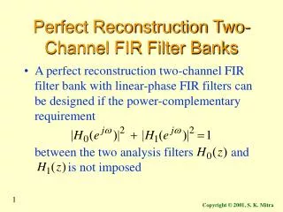
DFT/IDFT Filter Bank • Basic question is..: Downsampling introduces ALIASING, then how can PERFECT RECONSTRUCTION (PR) (i.e. y[k]=u[k-d]) be achieved ? • Next slides provide simple PR-FB example, to demonstrate that PR can indeed (easily) be obtained • Discover the magic of aliasing-compensation…. y[k]=u[k-d]? 4 4 G1(z) output = input H1(z) u[k] 4 4 G2(z) output = input H2(z) + 4 4 output = input G3(z) H3(z) 4 4 G4(z) output = input H4(z)
u[k] u[0],0,0,0,u[4],0,0,0,... 4 4 4 u[-1],u[0],0,0,u[3],u[4],0,0,... 4 4 4 u[-2],u[-1],u[0],0,u[2],u[3],u[4],0,... + + + 4 4 u[-3],u[-2],u[-1],u[0],u[1],u[2],u[3],u[4],... u[k-3] DFT/IDFT Filter Bank First attempt to design a perfect reconstruction filter bank - Starting point is this : convince yourself that y[k]=u[k-3] …
+ 4 4 u[k] 4 4 u[k-3] 4 4 4 4 DFT/IDFT Filter Bank - An equivalent representation is ... As y[k]=u[k-d], this can already be viewed as a (1st)perfect reconstruction filter bank (with lots of aliasing in the subbands!) All analysis/synthesis filters are seen to be pure delays, hence are not frequency selective (i.e. far from ideal case with ideal bandpass filters….) PS: Transmux version (TDM) see p.16
4 4 u[k] 4 4 u[k-3] + 4 4 4 4 DFT/IDFT Filter Bank -now insert DFT-matrix (discrete Fourier transform) and its inverse (I-DFT)... as this clearly does not change the input-output relation (hence perfect reconstruction property preserved)
4 4 u[k-3] 4 4 + 4 4 4 4 DFT/IDFT Filter Bank - …and reverse order of decimators/expanders and DFT-matrices (not done in an efficient implementation!) : =analysis filter bank =synthesis filter bank This is the `DFT/IDFT filter bank’. It is a first (or 2nd) example of a maximally decimated perfect reconstruction filter bank ! u[k]
u[k] DFT/IDFT Filter Bank What do analysis filters look like? (N-channel case) This is seen (known) to represent a collection of filters Ho(z),H1(z),..., each of which is a frequency shifted version of Ho(z) : i.e. the Hnare obtained by uniformly shifting the `prototype’ Ho over the frequency axis. : :
DFT/IDFT Filter Bank H1(z) Ho(z) H2(z) H3(z) The prototype filter Ho(z) is a not-so-great lowpass filter with significant sidelobes. Ho(z) and Hi(z)’s are thus far from ideal lowpass/bandpass filters. Hence (maximal) decimation introduces significant ALIASING in the decimated subband signals Still, we know this is a PERFECT RECONSTRUCTION filter bank (see construction previous slides), which means the synthesis filters can apparently restore the aliasing distortion. This is remarkable! Other perfect reconstruction banks : read on.. N=4
+ DFT/IDFT Filter Bank Synthesis filters ? synthesis filters are (roughly) equal to analysis filters… PS: Efficient DFT/IDFT implementation based on FFT algorithm (`Fast Fourier Transform’). *(1/N) N=4 : :
H0 H1 H2 H3 uniform H0 H3 non-uniform H1 H2 H0(z) IN H1(z) H2(z) H3(z) Maximally Decimated DFT-Modulated FBs Uniform versus non-uniform (analysis) filter bank: • N-channel uniform FB: i.e. frequency responses are uniformly shifted over the unit circle Ho(z)= `prototype’ filter (=one and only filter that has to be designed) Time domain equivalent is: • non-uniform = everything that is not uniform e.g. for speech & audio applications (cfr. human hearing) example: wavelet filter banks
H0(z) u[k] H1(z) H2(z) H3(z) i.e. Maximally Decimated DFT-Modulated FBs Uniform filter banks can be realized cheaply based on polyphase decompositions + DFT(FFT) (hence name `DFT-modulated FB) 1. Analysis FB If (N-fold polyphase decomposition) then
i.e. Maximally Decimated DFT-Modulated FBs where F is NxN DFT-matrix(and `*’ is complex conjugate) This means that filtering with the Hn’s can be implemented by first filtering with polyphase components and then DFT
u[k] i.e. Maximally Decimated DFT-Modulated FBs conclusion: economy in… • implementation complexity (for FIR filters): N filters for the price of 1, plus DFT (=FFT) ! • design complexity: Design `prototype’ Ho(z), then other Hn(z)’s are automatically `co-designed’ (same passband ripple, etc…) !
u[k] Maximally Decimated DFT-Modulated FBs • Special case: DFT-filter bank, if all En(z)=1 Ho(z) H1(z)
u[k] Maximally Decimated DFT-Modulated FBs • PS: with F instead of F* (see p.32), only filter ordering is changed Ho(z) H1(z)
u[k] u[k] 4 4 4 4 4 = 4 4 4 Maximally Decimated DFT-Modulated FBs • DFT-modulated analysis FB + maximal decimation = efficient realization !
+ + + Maximally Decimated DFT-Modulated FBs 2. Synthesis FB: similar.. y[k]
4 4 4 4 4 4 4 + + + + + + 4 Maximally Decimated DFT-Modulated FBs • Expansion + DFT-modulated synthesis FB : y[k] = = efficient realization ! y[k]
4 u[k] 4 4 4 y[k] + + + 4 4 4 4 Maximally Decimated DFT-Modulated FBs How to achieve Perfect Reconstruction (PR) with maximally decimated DFT-modulated FBs? polyphase components of synthesis bank prototype filter are obtained by inverting polyphase components of analysis bank prototype filter
4 u[k] 4 4 4 y[k] + + + 4 4 4 4 Maximally Decimated DFT-Modulated FBs Design Procedure : 1. Design prototype analysis filter Ho(z) (see Chapter-3). 2. This determines En(z) (=polyphase components). 3. Assuming all En(z) can be inverted (?), choose synthesis filters
Maximally Decimated DFT-Modulated FBs • Will consider only FIR prototype analysis filters, leading to simple polyphase decompositions. • However, FIR En(z)’s generally again lead to IIR Rn(z)’s, where stability is a concern… • Hence need for other/better design procedures
Other FBs… • Para-unitary perfect reconstruction filter banks • Cosine-modulated perfect reconstruction filter banks • Non-critically downsampled DFT-modulated perfect recinstruction filter banks • Non-uniform filter banks • Wavelet filter banks • Etc…


![AMR (Adaptive Multi-Rate]](https://cdn1.slideserve.com/2939494/amr-adaptive-multi-rate-dt.jpg)