Download
1 / 68
1.26k likes | 2.37k Vues
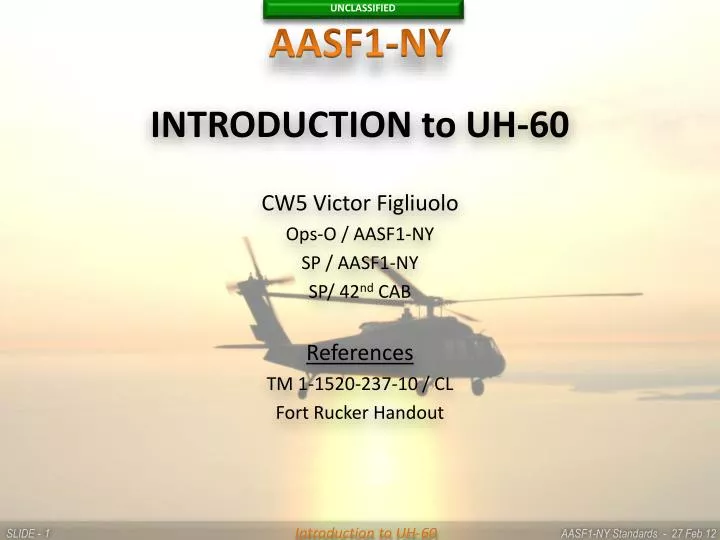
AASF1-NY. INTRODUCTION to UH-60 CW5 Victor Figliuolo Ops-O / AASF1-NY SP / AASF1-NY SP/ 42 nd CAB References TM 1-1520-237-10 / CL Fort Rucker Handout. INTRODUCTION to UH-60. OUTLINE Identify the characteristics of the UH-60 Blackhawk Helicopter

E N D
AASF1-NY • INTRODUCTION to UH-60 • CW5 Victor Figliuolo • Ops-O / AASF1-NY • SP / AASF1-NY • SP/ 42nd CAB • References • TM 1-1520-237-10 / CL • Fort Rucker Handout
INTRODUCTION to UH-60 • OUTLINE • Identify the characteristics of the UH-60 Blackhawk Helicopter • Identify the UH-60 Fuselage Section Special Features • Identify the UH-60 Cockpit Special Features • Identify the operational characteristics of the UH-60 Power Train System • Identify the operational characteristics of the UH-60 Landing Gear System
INTRODUCTION to UH-60 • TERMINAL LEARNING OBJECTIVE: • Identify major components / characteristics of the UH-60 Blackhawk Helicopter
INTRODUCTION to UH-60 • LEARNING STEP 1: Identify the characteristics of the UH-60 Blackhawk Helicopter • Army rotary-wing aircraft model designation: UH-60A+/L • Designer and model designation: Sikorsky, S-70 • Number and kind of engines: two; General Electric Company Model T700-GE-701D Turbo shaft • Fully articulated, four-bladed, main rotor head; rigid crossbeam, canted tail rotor-- two blades, four paddles • Non-retractable landing gear consists of two main gear assemblies and a tail wheel assembly
INTRODUCTION to UH-60 • LEARNING STEP 1: Identify the characteristics of the UH-60 Blackhawk Helicopter • Crew required • Minimum--pilot - copilot • Normal— • Pilot--right side of cockpit • Copilot--left side of cockpit • Crew chief/gunner--right side forward of cabin
INTRODUCTION to UH-60 • LEARNING STEP 1: Identify the characteristics of the UH-60 Blackhawk Helicopter • Mission • Troop assault • Aero-medical evacuation • Aerial recovery • Internal and external cargo
INTRODUCTION to UH-60 • LEARNING STEP 1: Identify the characteristics of the UH-60 Blackhawk Helicopter • Aircraft weights • Empty--approximately 11,000 pounds • Design weight--16,825 pounds • Maximum gross weight--22,000 pounds (modified) • Fuel load--approximately 360 gallons, two main tanks full (180 gallons each tank)
INTRODUCTION to UH-60 LEARNING STEP 2: Identify the UH-60 Fuselage Section Special Features
INTRODUCTION to UH-60 • LEARNING STEP 2: Identify the UH-60 Fuselage Section Special Features • Primary Structure - The primary structure is aluminum alloy. Some titanium and steel are used for firewalls and various fittings. Nonstructural members are primarily made of reinforced plastic • The fuselage may be broken down into the following sections: Nose section, Mid fuselage, Aft fuselage or transition section, Tail cone, Tail Rotor Pylon, Main Rotor Pylon
INTRODUCTION to UH-60 • LEARNING STEP 2: Identify the UH-60 Fuselage Section Special Features • Nose or cockpit section • Cockpit canopy, a kevlar reinforced plastic and aluminum structure • Pilot’s and copilot’s windshields. • Shatter resistant and scratchproof glass • Electrically heated for defogging and anti-icing • Center windshield- laminated glass, electrically anti-iced
INTRODUCTION to UH-60 • LEARNING STEP 2: Identify the UH-60 Fuselage Section Special Features • Nose or cockpit section • Pilot’s and copilot’s cockpit doors • - Aluminum, hinged, and capable of being jettisoned in an emergency • Contains either a fixed slide-open, or push open vent. The doors that have the push open vent window are designed so the pilot can pull the entire window into the cockpit for egress • Avionics Compartment • Avionics compartment door hinges up from bottom • Held open in two positions by support strut
INTRODUCTION to UH-60 • LEARNING STEP 2: Identify the UH-60 Fuselage Section Special Features • Cabin / Mid Fuselage • Includes crew chief/gunner stations and the troop-cargo compartment • Two outward facing seats are for the crew chief/gunners. Crew chief/gunner stations may have machine guns installed • Provisions for a maximum of 12 troop seats. • Provisions for MEDEVAC pedestal with a capacity of four to six litter patients
INTRODUCTION to UH-60 LEARNING STEP 2: Identify the UH-60 Fuselage Section Special Features
INTRODUCTION to UH-60 • LEARNING STEP 2: Identify the UH-60 Fuselage Section Special Features • Cabin / Mid Fuselage • Forward sliding crewchief/gunners window incorporates a nonflammable, stretchplex window split vertically into two panels • Defogged by heater outlet air directed from outer duct assembly onto window. • Sliding cargo doors on each side that cannot be jettisoned • Cargo door windows are jettisonable for use as for emergency exits. Moving the EMERGENCY EXIT handle aft, releases both windows. It may be necessary to push windows free
INTRODUCTION to UH-60 • LEARNING STEP 2: Identify the UH-60 Fuselage Section Special Features • Cabin / Mid Fuselage • Emergency Equipment consists of: • Three first aid kits • Two hand held (portable) fire extinguishers • Crash axe in cabin • The pilot and copilot flight controls are routed up each side of cabin • The main landing gear struts are mounted on each side of the helicopter, just aft of the crewchief/gunners windows
INTRODUCTION to UH-60 • LEARNING STEP 2: Identify the UH-60 Fuselage Section Special Features • Cabin / Mid Fuselage • Electrical junction boxes and relay panels located in cabin ceiling • Either a 9.5 Amp Hour Sealed Lead Acid Battery (SLAB) or a 5.5 Amp Hour Nickel Cadmium (NICAD) battery is located in forward cabin, left-hand side, aft of copilots seat • Cargo floor upper skin, cross-ply, unidirectional fiberglass; core is Nomex; bottom skin is woven fiberglass. Deck load limit is 300 pounds per square foot. • Cargo hook--8,000 pounds capacity • Two pitot tubes
INTRODUCTION to UH-60 • LEARNING STEP 2: Identify the UH-60 Fuselage Section Special Features • Aft Fuselage / Aft Transition Section • Two main fuel tanks #1 on left and #2 on right • Two equipment compartments located above fuel tanks, 20 by 20 by 40 inches, separated by fuel tanks enclosure, maximum capacity is 125 pounds each side. Cargo net restraints are available to restrain equipment
INTRODUCTION to UH-60 • LEARNING STEP 2: Identify the UH-60 Fuselage Section Special Features • Aft Fuselage / Aft Transition Section • Auxiliary Power Unit (APU) Hydraulic Accumulator or Accumulators • Used to start the APU using hydraulic pressure • Normally automatically re-pressurized by the backup hydraulic pump • The hand pump is used to manually re-pressurize the APU accumulator if it is below minimum required pressure for APU start or if the APU fails to start
INTRODUCTION to UH-60 LEARNING STEP 2: Identify the UH-60 Fuselage Section Special Features
INTRODUCTION to UH-60 • LEARNING STEP 2: Identify the UH-60 Fuselage Section Special Features • Aft Fuselage / Aft Transition Section • Steps on outside provide access to engines and APU above on left and right sides of aircraft
INTRODUCTION to UH-60 • LEARNING STEP 2: Identify the UH-60 Fuselage Section Special Features • Tail Cone • The tail cone, interconnecting the transition section and tail rotor pylon (station 644.62), supports the tail rotor drive shaft and tail pylon • Access panels allow inspection of tail landing gear attachments, pylon attachment bolts, tail rotor flight control cables and hydraulic lines, and tail landing gear • Tail rotor drive shafts mounted on top under hinged drives shaft covers
INTRODUCTION to UH-60 • LEARNING STEP 2: Identify the UH-60 Fuselage Section Special Features • Tail Rotor Pylon • The tail pylon is supported by and hinged to the tail cone section which allows folding of the pylon to the right for air transport • - The hinges are not critical structural members, because the tail pylon is secured to the tail cone in the flight position through the use of four bolts • - Eight close-tolerance bushings on the tail pylon hinge align with eight tapered pins in the tail cone hinge to ensure proper alignment
INTRODUCTION to UH-60 • LEARNING STEP 2: Identify the UH-60 Fuselage Section Special Features • Tail Rotor Pylon • Provides mounting points for the intermediate gearbox, the connecting drive shaft, the tail gearbox, the tail rotor assembly, the stabilator, and the dual electrical stabilator actuators • The drive shaft cover has a VHF/FM antenna built in to provide communications, this cover, opens to provide access to the tail drive shaft • Removable fairings on the pylon are provided for access to the intermediate and tail gear boxes, and tail rotor flight controls
INTRODUCTION to UH-60 • LEARNING STEP 2: Identify the UH-60 Fuselage Section Special Features • Tail Rotor Pylon • The trailing edge of the pylon has an aerodynamically shaped fairing, with a 7 degree camber to help unload tail rotor in forward flight • Retractable telescoping steps / hand-holds allow easy access to the tail rotor area. Accessed by pushing and rotating the cap 90 degrees counterclockwise, releasing the spring loaded tread, allowing the tread to extend
INTRODUCTION to UH-60 • LEARNING STEP 2: Identify the UH-60 Fuselage Section Special Features • Tail Rotor Pylon • The helicopter has a variable angle of incidence stabilator to enhance handling qualities • Level trim • Optimum attitude for flight
INTRODUCTION to UH-60 • LEARNING STEP 2: Identify the UH-60 Fuselage Section Special Features • Main Rotor Pylon
INTRODUCTION to UH-60 • LEARNING STEP 2: Identify the UH-60 Fuselage Section Special Features • Main Rotor Pylon • Covers area forward and around main gearbox. Front area of main rotor pylon slides forward on two tracks; gives access to servos, mixing unit, heater, hydraulic pumps, and various other hydraulic components. Allow smooth airflow induction for cooling aircraft major subsystem components • Steps and walkways aid in inspection and maintenance of the helicopter. Opening the engine doors and sliding the forward fairing forward reveals additional designated walkways/steps. Designated STEP AREAS have a non skid coating applied
INTRODUCTION to UH-60 • LEARNING STEP 2: Identify the UH-60 Fuselage Section Special Features • Main Rotor Pylon • Various types of latches are used to secure fairings, cowlings, and doors • Aft Main Rotor Pylon fairings hinge open to give access to APU, transmission oil cooler, two engine fire extinguisher containers/bottles, and the fuel selector valves • Oil Cooler. The oil cooler access panels open to allow inspection of various fuel lines, piping, valves and oil cooler and blower
INTRODUCTION to UH-60 • LEARNING STEP 2: Identify the UH-60 Fuselage Section Special Features • Main Rotor Pylon • Auxiliary Power Unit (APU) is aft and left of main gearbox • Provides pneumatic power for main engine starting and cabin heating • Electrical power for ground operations and in-flight emergency electrical power
INTRODUCTION to UH-60 • LEARNING STEP 2: Identify the UH-60 Fuselage Section Special Features • Main Rotor Pylon • Onboard Fire Extinguishing System • Controlled by either the pilot or copilot • Both bottles/containers may be used in either main engine or APU compartment • Thermal discharge indicator on the right side of aft fuselage will rupture, indicating that one or both containers experienced a thermal discharge
INTRODUCTION to UH-60 • LEARNING STEP 2: Identify the UH-60 Fuselage Section Special Features • Main Rotor Pylon • Onboard Fire Extinguishing System
INTRODUCTION to UH-60 • LEARNING STEP 2: Identify the UH-60 Fuselage Section Special Features • Main Rotor Pylon • Sliding Access Cover slides forward on two tracks; gives access to servos, mixing unit, heating system, hydraulic pumps, flight controls, main AC generators, and various other hydraulic components • Heater Mixing Unit is located on the forward right side, under the sliding main rotor pylon. The heater mixing unit is used to heat the cockpit and cabin and is operated by bleed air from the main engines, APU, or external source
INTRODUCTION to UH-60 • LEARNING STEP 2: Identify the UH-60 Fuselage Section Special Features • Main Rotor Pylon • Engine Cowling/Work Platform • The engine compartment doors hinge open, and provide a flat surface for maintenance use and inspection • Capable of supporting a static weight of 250 pounds
INTRODUCTION to UH-60 • LEARNING STEP 3: Identify the UH-60 Cockpit Special Features • A full set of flight controls for both pilot and co pilot • Energy Absorbing (EA) Pilot Seats are ballistic tolerant against 7.62 mm rounds • WARNING: Do not store any items below seats. Seats stroke downward during a crash and any obstruction will increase the probability and severity of injury. To prevent injury to personnel, do not release either the normal or emergency vertical adjust levers unless someone is sitting in the seat. The extension springs are under load at all times. With seat at lowest position, the vertical preload on the seat could be as high as 150 pounds. If no one is in the seat and vertical adjust lever (s) is released, the seat will be snapped to the highest stop. Anyone leaning over the seat or with hands on guide tubes above linear bearings, will be seriously injured.
INTRODUCTION to UH-60 • LEARNING STEP 3: Identify the UH-60 Cockpit Special Features • Energy Absorbing (EA) Pilot Seats • NOTE: The seat’s energy attenuators allow the seat to move vertically about 12 inches at between 14 and 19 G’s. • Emergency Vertical Release Levers allows crewmember to lower the seat to its lowest position • Emergency Tilt Release Levers allows crewmember to tilt seat aft to remove a disabled pilot • Horizontal and vertical adjustment levers allow seat adjustment of approximately 5 inches • Armored wing slides forward on outboard side
INTRODUCTION to UH-60 • LEARNING STEP 3: Identify the UH-60 Cockpit Special Features • The NO. 1 AC Primary and DC circuit breaker panels are located over the copilot's head; the NO. 2 AC Primary, AC Essential and NO. 2 DC Primary circuit breaker panels are located over the pilot's head • The Battery Bus circuit breaker panel is located on the lower center console on the aft left hand side • The DC Essential Bus circuit breaker panels are located on the rear of the upper overhead center console
INTRODUCTION to UH-60 • LEARNING STEP 3: Identify the UH-60 Cockpit Special Features • Instrument Panel. Engine and dual flight instruments are located on the one-piece instrument panel tilted forward 30°. Pilot and copilot instruments on outboard panels with identical layout. Non flight instrument display on center panel • Caution Advisory Panel just to the left of center with 82 indicator capsules. Cautions lights are amber, advisory lights are green • Master Warning Panels one in front of each pilot on the glare shield contain the following capsules labeled: MASTER CAUTION PRESS TO RESET (amber), #1 ENG OUT, #2 ENG OUT, FIRE, and LOW ROTOR RPM
INTRODUCTION to UH-60 • LEARNING STEP 3: Identify the UH-60 Cockpit Special Features • Vertical Instrument Display System (VIDS) consists of a vertical strip Central Display Unit (CDU), two vertical strip Pilot Display Units (PDU), and two Signal Data Converters (SDC) • (PDU’s) for both pilots displays the engine power turbine speed (% RPM 1 and 2), rotor speed (% RPM R), and torque (% TRQ 1 and 2). When the TEST switch is pressed, all PDU scale lamps should light and digital readouts should display 188. Three overspeed lights at the top will appear from left to right when a corresponding rotor speed of 127%, 137%, and 142% is reached
INTRODUCTION to UH-60 • LEARNING STEP 3: Identify the UH-60 Cockpit Special Features • The (CDU) contains instruments that display fuel quantity, transmission oil temperature and pressure, engine oil temperatures and pressures, turbine gas temperature (TGT), and gas generator speed (Ng) readings. When the Lamp Test Switch is pressed all CDU scale lamps should illuminate and the digital readouts should display 888
INTRODUCTION to UH-60 • LEARNING STEP 3: Identify the UH-60 Cockpit Special Features • The (CDU): • Digital readouts are also installed on the TOTAL FUEL, TGT, and Ng indicators • The No. 1 and No. 2 fuel quantity is displayed on the analog scales and the total fuel is displayed on a digital readout • The CDU and PDUs contain photocells that automatically adjust the lighting of the indicators with respect to ambient light
INTRODUCTION to UH-60 • LEARNING STEP 3: Identify the UH-60 Cockpit Special Features • The (CDU): • A failure of any SDC or CDU processing circuit, display driver module, or logic power supply, will cause the associated display channel to turn off or switch to the backup processor, and will light the associated CHANNEL failure light • Failure of the lamp power supply within a SDC, will cause every second display light on the CDU to go off. If a digital processor fails, all digital displays will go off
INTRODUCTION to UH-60 LEARNING STEP 3: Identify the UH-60 Cockpit Special Features
INTRODUCTION to UH-60 • LEARNING STEP 3:Identify the UH-60 Cockpit Special Features • The Upper Console, overhead between pilot and copilot, contains engine controls, fire emergency controls, heater and windshield wiper controls, internal and external light controls, electrical systems, and miscellaneous helicopter system controls • The Lower Console, next to the base of the instrument panel and extending through the cockpit between the pilot and copilot, is easily reached by either pilot. The console is arranged with communication panels, navigational panels, and flight attitude/stability controls
INTRODUCTION to UH-60 • LEARNING STEP 3: Identify the UH-60 Cockpit Special Features • Miscellaneous Switch Panel consists of three push-button switches marked FUEL IND TEST, TAIL WHEEL, and GYRO ERECT, and one toggle switch marked TAIL SERVO/NORMAL/BACKUP
INTRODUCTION to UH-60 • LEARNING STEP 3: Identify the UH-60 Cockpit Special Features • The FUEL IND TEST SWITCH, when pressed in and held, causes digital readout and strip indicators to change and caution lights to flash, to test the fuel quantity indicating system • The TAIL WHEEL switch unlocks and locks the TAIL WHEEL in a trail position, and indicates LOCK or UNLK • The GYRO ERECT initiates a higher voltage to the attitude indicating system's vertical gyros • TAIL SERVO NORMAL/BACKUP Switch allows selection of #1 or #2 tail rotor servo
INTRODUCTION to UH-60 • LEARNING STEP 3: Identify the UH-60 Cockpit Special Features • Stabilator/Automatic Flight Control Panel • The panel contains a MAN SLEW switch, a TEST button, and AUTO CONTROL RESET switch with a push-to-reset feature. • The automatic flight control portion of the panel controls the Automatic Flight Control System(AFCS) which enhances the stability and handling qualities of the helicopter.
INTRODUCTION to UH-60 • LEARNING STEP 4: Identify the operational characteristics of the UH-60 Power Train System • The UH-60 employs two General Electric T700-GE-700 Turbo Shaft engines with an input drive shaft that is approximately 18 inches long and connects the engines power turbine output to the input module on main gearbox • The engine is divided into four modules: cold section, hot section, power turbine section, and accessory section
INTRODUCTION to UH-60 • LEARNING STEP 4: Identify the operational characteristics of the UH-60 Power Train System • The main transmission is mounted on top of the cabin between the two engines • The main transmission assembly consists of five modules • The Main Module • Two Input Modules • - Two Accessory Modules (drives the following accessories): • The No. 1 & 2 Hydraulic Pump Modules • The No. 1 & 2 AC Generators
INTRODUCTION to UH-60 • LEARNING STEP 4: Identify the operational characteristics of the UH-60 Power Train System • Intermediate gearbox is bolted to top of pylon, changes angle of drive, and reduces RPM • The tail gear box mounts the tail rotor and enables pitch changes of tail rotor blades, changes angle of drive and gives a gear reduction