Download
1 / 16
160 likes | 291 Vues
m. Muons, Inc. Loaded Pillbox Cavity. Milorad Popovic. (with Mike, Chuck, Katsuya, Al and Rol). m. Muons, Inc. Motivation. To fit pressurized cavities in HCC, size of cavity has to be reduced

E N D
m Muons, Inc. Loaded Pillbox Cavity Milorad Popovic (with Mike, Chuck, Katsuya, Al and Rol) Muon Collider Design Workshop, Jefferson Lab
m Muons, Inc. Motivation To fit pressurized cavities in HCC, size of cavity has to be reduced 800 MHz (from Katsuya) Maximum RF cavity radius = 0.08 m, (pillbox cavity 0.143)Radius of effective electric field (95 % from peak) = 0.03 m 400 MHz:Maximum RF radius = 0.16 m (pillbox cavity 0.286) Radius of effective electric field = 0.06 mOptimum electric field gradient = 16 MV/m For Pill Box Cavity, resonant frequency is Muon Collider Design Workshop, Jefferson Lab
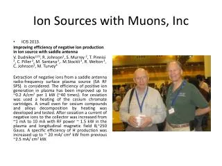
m Muons, Inc. Dielectric Loaded RF Cavities New type of cavity is suggested. The idea came from conversation with Chuck and Yonehara. I was told that Al suggested something like this. Cu/Steel ceramics Vaccum/H/He Muon Collider Design Workshop, Jefferson Lab
m Muons, Inc. SuperFish Model Muon Collider Design Workshop, Jefferson Lab
m Muons, Inc. 400MHz Cavity Muon Collider Design Workshop, Jefferson Lab
m Muons, Inc. 400MHz Cavity Ez at center of cavity R(cm) Muon Collider Design Workshop, Jefferson Lab
m Muons, Inc. 361MHz Cavity Muon Collider Design Workshop, Jefferson Lab
m Muons, Inc. HCC Concept Central Orbit and Beam Envelope Set of Coils Basic Building Block can be Cavity + Coil Muon Collider Design Workshop, Jefferson Lab
m Detectors Cavity + Coil Cryostat Vessel Muons, Inc. Power in Signals out Feedthroughs MANX + RF ? MICE will have ~?MV @200MHz Muon Collider Design Workshop, Jefferson Lab
m Muons, Inc. Other Applications May be we can use this type of cavity for Neuffer’s Phase Rotation Canal. This was Cary Yoshikawa suggestion. The canal needs many cavities in range from ~300 to 200MHz. We can use, let say two sizes of Pill Box Cavity (same size different dielectric!) and adjust frequency in between using different iner radius, re-entrant nose cones! Muon Collider Design Workshop, Jefferson Lab
m Muons, Inc. Cavities for Neutrino Factory Schematic of the Neutrino Factory front-end transport system. Initial drift (56.4 m), the varying frequency buncher (31.5m), The phase-energy (-E) rotator (36m) , a cooling section. (A 75m cooling length may be optimal.) Muon Collider Design Workshop, Jefferson Lab
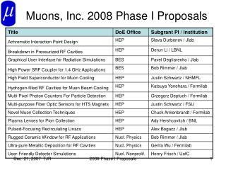
m Muons, Inc. What is Next SBIR Phase I-SBIR/STTR Fiscal Year 2009 (All information provided on this page is subject to release to the public.) NAME of PRINCIPAL INVESTIGATOR: Michael Neubauer PHONE NUMBER: (707) 360-5038 PROJECT TITLE: 46a Dielectric Loaded RF Cavities Main Issues Loss tangent tan d = 1/Qdielectric-1/Qair Loss tangents of specially formulated alumina with TiO2 have been reported to be close to sapphire at 1e-5 . So it is easy to see that today’s ceramics may be used in this novel idea without suffering a great deal in cavity Q at low frequencies. The other problem with ceramics in vacuum with beams is that of surface charging of the ceramic. And again, much work has been done in coatings, from Chromium Oxide to TiN to, more recently, ion implantation Air gap between the dielectric and metal plates will be one of the issues that must be tested experimentally Muon Collider Design Workshop, Jefferson Lab
m Muons, Inc. • May be ceramics can play additional role, making volume of Hydrogen smaller and making cavity stronger so the walls do not have to be as thick as without ceramics. • RF power can be fed using loop between two rings. • Cavities can be put next each other so the side wall can be made thin • May be we should do experiment in the MTA, with solenoid! Muon Collider Design Workshop, Jefferson Lab
m Muons, Inc. Test Cavity Muon Collider Design Workshop, Jefferson Lab
m Muons, Inc. Cavity + Coil Compact, Tunable RF Cavities
m Muons, Inc. Model Cavity Copper 9cm 15cm 6.7cm Muon Collider Design Workshop, Jefferson Lab