Download
1 / 58
590 likes | 839 Vues
BACKGROUND INFORMATION ON CHEST TUBES. This is not a summary of a skill!. For your skill on Chest Tubes, you were given a handout. I wanted to provide you with some background information on chest tubes This was taken from your textbook: Perry, Potter & Ostendorf .

E N D
This is not a summary of a skill! • For your skill on Chest Tubes, you were given a handout. • I wanted to provide you with some background information on chest tubes • This was taken from your textbook: Perry, Potter & Ostendorf. • Again, this is just for your information and this is not the summary of any particular skill!
INTRODUCTION • The chest cavity is a closed structure bound by muscle, bone, connective tissue, vascular structures, and the diaphragm. • This cavity has three distinct sections, each sealed from the others; one section for each lung and a third section for the mediastinum, which surrounds structures such as the heart, esophagus, trachea, and great vessels.
INTRODUCTION – CONT’D • The lungs are covered with a membrane called the visceral pleura. • The interior chest wall is lined with a membrane called the parietal pleura. • The space between the visceral and parietal pleura is called the pleural space and is filled with approximately 7-20 mL of lubricating fluid to help the pleura slide during respiration (Twedell, 2009).
INTRODUCTION – CONT’D • During inspiration the intercostal muscles pull outward, and the diaphragm contracts and pulls downward, thereby increasing the size of the chest cavity. • As a result an increase in the mount of negative pressure (vacuum effect) is exerted in the intra-pleural space. • During inspiration increased negative pressure pulls the lungs against the expanded chest cavity, increasing their size. • The expanding lungs cause the intra-pulmonic (alveolar) pressure to fall lower than atmospheric pressure, thus increasing the negative pressure within the lungs.
INTRODUCTION – CONT’D • This change in pressure causes air to rush into the lungs until the intra-pulmonic pressure is equal to the pressure in the atmosphere. • When the chest cavity stops expanding and the lungs are full of air, the respiratory muscles and diaphragm relax and return the chest cavity to its resting stage. • Expiration (exhalation) is a passive process that results from relaxation of the inspiratory muscles that decrease the space in the chest cavity.
INTRODUCTION – CONT’D • Trauma, disease, or surgery can result in air, blood, pus, or lymph fluid leaking into the intra-pleural space, creating a positive pressure that collapses lung tissue (Durai et al., 2010). • Small leaks (24% or less) are sometimes absorbed spontaneously and may not require a chest tube. • The usual intervention for larger leaks is a chest tube to remove air and fluid from the pleural space, prevent air and/or fluid from re-entering the pleural space, and re-establish normal intra-pleural and intrapulmonary pressures.
INTRODUCTION – CONT’D • PLEURAL EFFUSION: When a number of clinical conditions such as cancer, infection, pancreatitis, connective tissue disease, autoimmune diseases, asbestos exposure, certain drugs or collagen vascular diseases increase pleural fluid entry or decrease fluid exit from the lung. • When present, a patient usually needs a diagnostic thoro-centesis and pleural fluid analysis to determine the cause of the exudate (see Chapter 44) (Twedell, 2009). • Patients usually need one or more chest tubes to promote drainage of the excess fluid and lung expansion.
INTRODUCTION – CONT’D • PNEUMOTHORAX -is collapse of the lung caused by a collection of air in the pleural space. • The loss of negative intra-pleural pressure causes the lung to collapse. • A variety of mechanisms cause a pneumothorax. • A traumatic pneumothorax develops as a result of penetrating chest trauma such as a stabbing (open) or the chest striking the steering wheel in an automobile accident (closed). • A spontaneous or primary pneumothorax sometimes occurs from the rupture of a small bleb (blister) on the surface of the lung or an invasive procedure such as insertion of a subclavian intravenous (IV) line.
INTRODUCTION – CONT’D • Secondary pneumothorax occurs because of underlying disease such as emphysema. • A patient with a pneumothorax usually feels sharp chest pain that worsens on inspiration or coughing because atmospheric air irritates the parietal pleura. • As a pneumothorax worsens, a patient will experience easy fatigue, a rapid heart rate and low blood pressure (U.S. National Library of Medicine, 2011).
INTRODUCTION – CONT’D • A tension pneumothorax, a life-threatening situation, occurs from a rupture in the pleura when air accumulates in the pleural space more rapidly that it is removed. • (Briggs, 2010). • The pleural space functions as a one-way valve, causing an increase in the amount of air and pressure. • If left untreated, the lung on the affected side collapses; and the mediastinum shifts to the opposite (unaffected side), leading to tracheal deviation, reduced venous return, and subsequent decrease in cardiac output. • Tracheal deviation is a late sign and may be absent in some cases (Bethel, 2009).
INTRODUCTION – CONT’D • A patient has sudden chest pain, a fall in blood pressure, tachycardia, acute pleuritic pain, diaphoresis, dry cough and cardiopulmonary arrest can occur. • Patient with chest trauma, fractured ribs, invasive thoracic bedside procedure (e.g., insertion of central lines), and those on high-pressure mechanical ventilation are at risk for tension pneumothorax (Bethel, 2008). • If emergent treatment is required, a needle decompression is achieved with a large-gauge needle (14 or 16 gauge) inserted into the second intercostal space, mid-clavicular line. • A “hissing” sound is noted, followed by a rapid stabilization of the patient’s vital signs and respiratory status
INTRODUCTION – CONT’D • A hemothorax is collapse of the lung caused by an accumulation of blood and fluid in the pleural cavity between the chest wall and the lung, usually as a result of trauma. • It produces a counter pressure and prevents the full expansion of the lung. • A hemothorax is also caused by rupture of small blood vessels from inflammatory process such as pneumonia or tuberculosis.
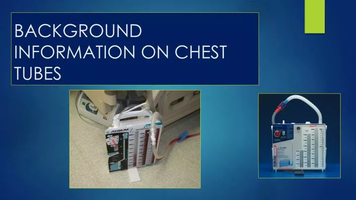
INTRODUCTION – CONT’D • In addition to pain and dyspnea, signs and symptoms of shock can develop if blood loss is severe. • Chest tube insertion is the treatment for most types of effusions, pneumothorax, hemothorax, and postoperative chest surgery or trauma. • A chest tube is a large catheter inserted through the thorax to remove fluid (effusions), blood (hemothorax), and/or air (pneumothorax). • Small-bore chest tubes (12 to 20 Fr) are sufficient to remove air, and large-bore (24 to 32 Fr) tubes are needed to remove fluid and blood. • In some settings the traditional reusable glass three-bottle system is still used but rarely.
INTRODUCTION – CONT’D • Clear, plastic, disposable containers are most common (Durai et al., 2010). • The newest system available is the mobile chest drain, which allows a patient to move about with less restriction. • Regardless of the system used, the principles of patient management are the same. • A pleural chest tube is inserted when air or fluid enters the pleural space, compromising oxygenation or ventilation. • A closed chest drainage system with or without suction is attached to the chest tube to promote drainage of air and fluid. • Lung re-expansion occurs as the fluid or air is removed from the pleural space (Briggs, 2010; Twedell, 2009).
INTRODUCTION – CONT’D • The location of the chest tube indicates the type of drainage expected. • Apical (second or third intercostal space) and anterior chest tube placement promotes removal of air. • Because air rises, these chest tubes are placed high, allowing evacuation of air from the intrapleural space and lung re-expansion. • The air is discharged into the atmosphere, and there is little or no drainage in the collection chamber.
INTRODUCTION – CONT’D • Chest tubes placed low (usually in the fifth or sixth intercostal space) and posterior or lateral drain fluid. • Fluid in the intrapleural space is affected by gravity and localizes in the lower portion of the lung cavity. • Tubes placed in these positions drain blood and fluid. • Frequently applying suction helps with this drainage.
INTRODUCTION – CONT’D • Fluid drainage is expected after open-chest surgery and with some chest trauma. • A mediastinal chest tube is placed in the mediastinum, just below the sternum, and is connected to a drainage system. • This tube drains blood or fluid, preventing its accumulation around the heart. • A mediastinal tube is commonly used after open-heart surgery.
SAFETY GUIDELINES • 1. Document patient’s baseline vital signs, oxygen saturation, lung sounds, and respiratory status. Changes in vital signs or respiratory status often indicate a malfunction of a chest drainage system. • 2. Observe the water seal for intermittent bubbling from its U tube or a rise and fall of fluid that is synchronous with respirations (Briggs, 2010). For example, in a non-mechanically ventilated patient the fluid level rises during inspiration and falls during expiration. When a patient is on a mechanical ventilator, the opposite occurs. • A. Constant bubbling in the water seal or a sudden, unexpected stoppage of water-seal activity is considered abnormal and requires immediate attention (Briggs, 2010). • B. Unexpected stoppage of activity may indicate a blockage or re-expansion. In these situations immediate attention and correction are indicated. After 2 to 3 days, tidaling or bubbling on expiration is expected to stop, indicating that the lung has re-expanded (Briggs, 2010).
SAFETY GUIDELINES • 3. In a waterless system look for a rise and fall of fluid in the diagnostic air-leak indicator synchronous with respirations. Constant left-to-right bubbling (when facing the indicator) or violent rocking is considered abnormal and indicates an air leak.
SAFETY GUIDELINES • 4. Note the expected amount of chest tube drainage, and monitor drainage on a regular basis (e.g., every hour initially and then every 4 hours). At the end of the shift, make a mark to indicate the fluid level with the date and time on the side of the drainage collection chamber. Note the drainage amount as output. • A. A sudden decrease in the amount of chest tube drainage can indicate a possible clot or obstruction in the chest tube. • B. Notify a health care provider when there is a sudden increase of more than 250 mL of drainage over 1 hour, which can indicate fresh bleeding from the thorax (Durai et al., 2010). • C. Drainage from a pneumothorax is generally limited. Any fluid buildup is caused by chest tube insertion trauma. The chest tube promote the removal of air from the intrapleural space.
SAFETY GUIDELINES • 5. Know the expected color of the drainage. Drainage from recent open-chest surgery is initially bright red and gradually becomes serous as the postoperative course continues. Blood-tinged fluid usually indicates malignancy, pulmonary infarction, or severe inflammation. Frank blood indicates a hemothorax. Pus indicates an empyema, which is a collection of pus in the pleural cavity (Briggs, 2010). • 6. In the water-seal system observe for constant, gentle bubbling in the suction control chamber when it is connected to suction. In the waterless system a designated amount of suction is maintained by setting the suction source and dialing the prescribed suction level in the float ball column.
SAFETY GUIDELINES • 7. Assess both types of systems for air leaks. If an air leak exists, determine whether it is in the patient (patient-centered air leak) or in the chest tube system (system-centered air leak). To rule out an air leak as patient-centered, you assess the patient’s respiratory status. Document and report any changes to lung sounds, pulse oximetry, respiratory rate, or mentation. • Remember that continuous bubbling in the water-seal chamber with an absence of bubbles in the suction control chamber indicates that there is a leak in the system (Briggs, 2010). Ensure that all tubing connections are tight.
MANAGING CLOSED DRAINAGE SYSTEM • There are two types of commercial drainage systems: the water-seal and the waterless system. • This skill reviews the nursing responsibilities and interventions related to the safe management of the chest tubes. • Review the roles and responsibilities of the health care provider for chest tube placement.
TWO-CHAMBER WATER-SEAL SYSTEM • On expiration fluid or air is forced out of the intrapleural space. • Suction pulls air or fluid through the chest tube into the drainage collection chamber. • On entering the drainage collection chamber, this fluid or air displaces the air present in the chamber by pushing it through the water seal and out of the system into the atmosphere.
TWO-CHAMBER WATER-SEAL SYSTEM – CONT’D • The water-seal chamber is left open to air to drain. • If the tubing is clamped, there is no mechanisms for air to vent. • To maintain the water-seal system, the chest tube system must remain upright. • When it is tipped or overturned, the water seal is disrupted.
THREE-CHAMBER WATER-SEAL SYSTEM • If suction is used, the three-chamber water-seal system is set up with the suction control chamber added. • A prescribed amount of sterile fluid (e.g., 20 cm of water) is poured into the suction control chamber, which is then attached to a suction source by tubing. • The amount of sterile water added depends on manufacturer recommendations. • The chamber is filled to the set volume for the prescribed amount of suction.
THREE-CHAMBER WATER-SEAL SYSTEM – CONT’D • Sterile water is added several times a day because of evaporation. • As the fluid level decreases, the amount of suction also declines. • The wall or portable bottle exhibits a continuous, gentle bubbling. • This provides the prescribed amount of suction (negative pressure). • If the suction source delivers more negative pressure than the suction control chamber water level allows, there is no danger because atmospheric air is pulled into the suction control chamber through an inlet, causing the excess suction to dissipate.
THREE-CHAMBER WATER-SEAL SYSTEM – CONT’D • The extra air pulled into the chamber causes vigorous bubbling. • If this occurs lower the suction source setting to reduce noise and evaporation of the fluid. • The absence of bubbling indicates that no suction is being exerted into the system. • Raise the suction setting to restore gentle bubbling. • The middle chamber of a traditional chest drainage system is the water seal.
THREE-CHAMBER WATER-SEAL SYSTEM – CONT’D • The water seal allows air to exit from the pleural space on exhalation and prevents it from entering the pleural cavity or mediastinum on inhalation. • When the appropriate amount of sterile water is added, a 2-cm water seal is established. • To maintain effective water seal the chest drainage unit must remain upright, and you must monitor the water level in the water-seal chamber to check for evaporation. • Bubbling in the water-seal chamber indicates an air leak.
WATERLESS SYSTEM : TWO-CHAMBER WATERLESS SYSTEM • The principles of the waterless system are similar to those of the water-seal system except that fluid is not required for setup. • Because water is not used, accidentally tipping the system does not compromise the patient’s condition. • The water seal is replaced by a one-way valve located near the top of the system. • Most of the container serves as the drainage chamber.
WATERLESS SYSTEM : TWO-CHAMBER WATERLESS SYSTEM – CONT’D • The suction chamber does not depend on water. • Instead it contains a float ball, which is set by a suction control dial after the suction source is turned on. • A diagnostic air-leak indicator is located on the face of the unit. • It requires the addition of 15 mL of fluid for visualization.
WATERLESS SYSTEM : TWO-CHAMBER WATERLESS SYSTEM – CONT’D • The function of the indicator is to identify one of the following: • 1. The lung is expanding normally. This is indicated by a gentle tidaling of the fluid in the diagnostic indicator. • 2. The lung is probably re-expanded if after 2 or 3 days the tidaling has stopped. • 3. There is an air leak in the system if, when facing the system, the observer sees the fluid bubbling left to right. Locate and correct the source of the air leak.
THREE-CHAMBER WATERLESS SYSTEM • When suction is ordered, attach the suction chamber port to the suction source by tubing, turn the suction on , and set the float ball to the prescribed setting. • If the float ball does not rise to the prescribed level, increase the suction source setting until it does. • The system is now functioning with suction. • There are usually two suction settings: • One at either the suction control chamber or the float ball setting and the other at the suction source. • The chamber or float ball setting is a safety factor to reduce the possibility that the intrapleural tissue receive too much suction, causing injury.
DRY SUCTION SYSTEM • Dry suction control system provides many advantages including higher suction pressure levels, easy setup, and the lack of continuous bubbling, which provides for quiet operation. • There is no fluid to evaporate, which decreases the amount of suction necessary. • A self-compensating regulator controls dry suction units. • A dial is set to the prescribed suction control setting. • These units are preset to 20 cm of water pressure, but they are adjustable from 10 to 20 cm of water pressure, but they are adjustable from 10 to 40 cm. • However, the dry suction control systems require or have pre-sealed sterile water in the water-seal chamber (Atrium, 2010).
NURSING DIAGNOSIS EXAMPLES • 1. Anxiety • 2. Acute Pain • 3. Impaired Gas Exchange • 4. Risk for Infection
PLANNING • 1. Expected outcomes following completion of procedure: • Patient is oriented and less anxious • Hypoxia is relieved • Vital signs are stable • Decreased hypoxia improves vital sign measures.
PLANNING – CONT’D • Patient reports no chest pain. • Re-expansion of lung reduces chest pain. • Breath sounds are auscultated in all lobes. Lung expansion is symmetric, pulse oximetry (SpO2) is stable or improved, and respirations are non-labored. • Chest tube remains in place, and chest drainage system remains airtight. • Indicates correct placement and patency of chest tube drainage system.
PLANNING – CONT’D • Gentle tidaling (fluctuations or rocking) is evident in water-seal or diagnostic indicator. • Indicates that system is functioning normally. Reflects changes in intrapleural pressure.
EVALUATION • 1. Evaluate patient for decreased respiratory distress and chest pain. Auscultate patient’s lungs and observe chest expansion. • Determines status of lung expansion. • 2. Monitor vital signs and pulse oximetry. • Determines if level of oxygenation has improved. • 3. Reassess patient’s level of comfort on scale of 0 to 10, comparing level with comfort before chest tube insertion. • Indicates need for analgesia. Patient with chest tube discomfort hesitates to take deep breaths and as a result is at risk for pneumonia and atelectasis.
EVALUATION – CONT’D • 4. Evaluate patient’s ability to use deep-breathing exercises while maintaining comfort. • Indicates patient’s ability to promote lung expansion and prevent complications. • 5. Monitor continued functioning of system as indicated by reduction in amount of drainage, resolution of air leak, and complete re-expansion of the lung. • Detects early signs of system complications or indicates possible removal of chest tube.
UNEXPECTED OUTCOMES • 1. Patient develops respiratory distress. Chest pain, a decrease in breath sounds over affected and non-affected lungs, marked cyanosis, asymmetric chest movements, presence of subcutaneous emphysema around tube insertion site or neck, hypotension, tachycardia, and/or mediastinal shift, are critical and indicate a severe change in patient status such as excessive blood loss or tension pneumothorax. • Related Interventions: • Notify health care provider immediately. • Collect set of vital signs and pulse oximetry • Prepare for Chest X-ray • Provide oxygen as ordered.
UNEXPECTED OUTCOMES – CONT’D • 2. Air leak is unrelated to patient’s respirations • Notify health care provider • See Table 26-3 for determining source of an air leak and problem solving (discussed later in this power point presentation). • 3. There is no chest tube drainage: • Observe for kink in chest drainage system. • Observe for possible clot in chest drainage system. • Observe for mediastinal shift or respiratory distress (medical emergency). • Notify health care provider.
UNEXPECTED OUTCOMES – CONT’D • 4. Chest tube is dislodged. • Immediately apply pressure over chest tube insertion site. • Have assistant obtain sterile petroleum gauze dressing. Apply as patient exhales. Secure dressing with tight seal. • 5. Substantial increase in bright red drainage is observed. • Obtain vital signs. • Monitor drainage. • Assess patient’s cardiopulmonary status. • Notify health care provider.