Download
1 / 35
530 likes | 1.22k Vues
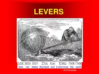
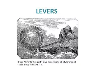
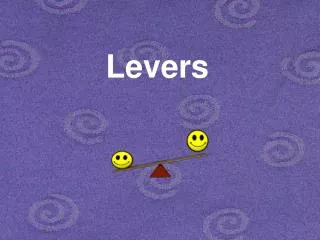
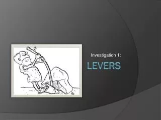
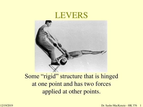
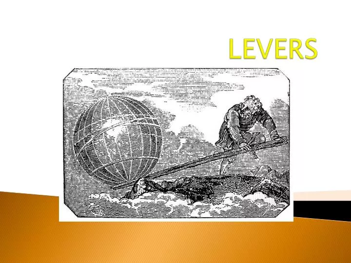
LEVERS. Definition & Concept. Lever is a simple machine which operates according to the principles of moment. Lever is a rigid bar which can rotate about a fixed point when a force is applied to overcome a resistance. Definition & Concept.

E N D
Definition & Concept • Lever is a simple machine which operates according to the principles of moment. • Lever is a rigid bar which can rotate about a fixed point when a force is applied to overcome a resistance.
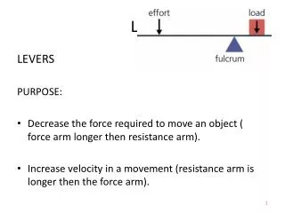
Definition & Concept • Lever – A bar that is free to move about a fixed point • Parts of a lever • Fulcrum – The fixed point of a lever • Effort Arm – The part of the lever that the effort force is applied to (measured from the fulcrum to the point at which the force is applied) • Resistance Arm – The part of the lever that applies the resistance force (measured from the fulcrum to the center of the resistance force)
Function of Lever • Lever perform two important functions • They are used either to overcome a larger resistance than the effort applied. OR • To increase the distance a resistance can be moved through by applying greater effort than the resistance. • Note: When there is no motion, the effort turning effect equals the resistance turning effect, and the lever system is said to be balanced.
Lever Arms • Lever arms are commonly defined as the portion of the lever between the fulcrum and the force point. • The effort arm is the distance between the fulcrum and the effort point. • The resistance arm is the distance between the fulcrum and the resistance point.
By using the length of the effort arm and the resistance arm we can find the ideal mechanical advantage. Ideal Mechanical Advantage (IMA) – if there were no energy lost due to friction the IMA=length of effort arm=le.length of resistance armlr Mechanical Advantage
There are 3 types of levers • 1st Class Levers • 2nd Class Levers • 3rd Class Levers
1st Class Lever • The fulcrum is located between the Fe and the Fr. First class levers can multiply force and distance. • Examples: Scissors, see-saw
2nd Class Lever • Resistance is located between the effort force and the fulcrum. These levers multiply the force but the direction stays the same. • Example: Wheelbarrow
The effort force is located between the fulcrum and the resistance. The effort arm is always shorter than the resistance arm so it cannot multiply the force and the MA is always less than 1. Examples: Rake, hockey stick 3rd Class Lever
Principle of Lever • A lever of any class will balance when the product of the effort arm and effort equal to the product of resistance arm and resistance. • This is known as principle of levers. • It enables us to calculate the amount of effort needed to balance a known resistance.
Cont. • If any three of the four values are known the remaining one can be calculated by using the following equation. E x EA = R x RA Where: E = Effort EA = Effort Arm R = Resistance RA = Resistance Arm
Cont. • A lever whose effort arm is longer of the two whether it be a Ist or IInd class lever, is said to favor force. (Less effort is required to overcome a resistance ) • Conversely, a lever whose resistance arm is longer, whether it be a Ist or IIIrd class lever, is said to favor speed and distance.
Relation of Speed to Range of Movement of Levers • In angular movement speed and range are interdependent. • For instance if two IIIrd class lever of different length moves through a 40 degree angle at the same angular velocity, the tip of the longer lever will be traveling a greater distance than the tip of the shorter lever.
Cont. • Since both the lever is traveling their distance in equal time the longer lever must be traveling faster than the shorter lever.
Selection of Lever • Skill in motor performance depends upon the effective selection and use of levers, both internal and external. • Long golf clubs are selected for distance and shorter clubs for accuracy at close range. • Heavy base ball bats are chosen by those with good strength whereas children are often taught tennis with short handled racquets
Cont. • In most instance the external levers are designed for a specific purpose and are selected accordingly. • Whereas the levers in the human body are not designed for one action or purpose, so the sports person must use his body parts as a lever as per the requirement.
Cont. • Shorter body levers increases angular velocity while the positioning of body parts to form a long position favor linear speed and range of motion.
Identification and Analysis of Levers • For identifying a lever one should find the following answers: • What is the location of the fulcrum • Where is the effort point and where is the resistance point • What is the length of effort arm • What is the length of resistance arm • What are the relative length of effort and resistance arm • What kind of movement does it favors
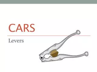
Levers QuizUse the following slides to quiz yourself on how how well you can match commonly used items with their correct class of lever.
Chose the correct Lever classification for the tool pictured below. Class 1 Class 2 Class3
Chose the correct Lever classification for the tool pictured below. Class 1 Class 2 Class 3
Chose the correct Lever classification for the tool pictured below. Class 1 Class 2 Class 3
Chose the correct Lever classification for the tool pictured below. Class 1 Class 2 Class 3
Chose the correct Lever classification for the tool pictured below. Class 1 Class 2 Class 3
Chose the correct Lever classification for the tool pictured below. Class 1 Class 2 Class 3
Chose the correct Lever classification for the tool pictured below. Class 1 Class 2 Class 3
Chose the correct Lever classification for the tool pictured below. Class 1 Class 2 Class 3
Chose the correct Lever classification for the tool pictured below. Class 1 Class 2 Class 3
Chose the correct Lever classification for the tool pictured below. Class 1 Class 2 Class 3
Chose the correct Lever classification for the tool pictured below. Class 1 Class 2 Class 3
Chose the correct Lever classification for the tool pictured below. Class 1 Class 2 Class 3