Download
1 / 29
290 likes | 468 Vues
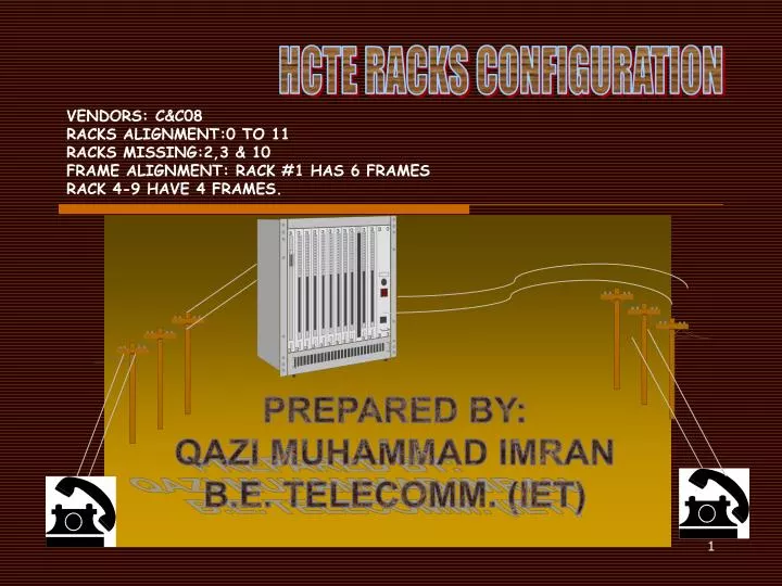
HCTE RACKS CONFIGURATION. VENDORS: C&C08 RACKS ALIGNMENT:0 TO 11 RACKS MISSING:2,3 & 10 FRAME ALIGNMENT: RACK #1 HAS 6 FRAMES RACK 4-9 HAVE 4 FRAMES. PREPARED BY: QAZI MUHAMMAD IMRAN B.E. TELECOMM. (IET). PROFILE C&C08. MODULAR STRUCTURE. MODULES. CM: Communication Module

E N D
HCTE RACKS CONFIGURATION VENDORS: C&C08RACKS ALIGNMENT:0 TO 11RACKS MISSING:2,3 & 10FRAME ALIGNMENT: RACK #1 HAS 6 FRAMESRACK 4-9 HAVE 4 FRAMES. PREPARED BY: QAZI MUHAMMAD IMRAN B.E. TELECOMM. (IET)
MODULES • CM: Communication Module • AM: Administration Module • FAM: Front AM • BAM: Back AM • SPM: Service Processing Module • SRM: Shared Resource Module • SM: Switching Module
Switching Module: • Independent switching function and handles traffic intra module • Provides various services interface • Performs a variety of functions including database management, call processing, ,maintenance and operation.
Remote Switching Module: • Same as SM, difference is that SM links through 40 meter optical interface while RSM has standard E1 interface and may use SDH, specifically STM-1.
FRONT ADMINISTRATION MODULE • Management of inter-sim call connection. • Provides open management interface to terminal system. • It performs routine management tasks like ticket recording and traffic statistics.
COMMUNICATION MODULE • It consists of central switching network and inter-module communication interface. • Also provides inter SM speech channels and signaling links.
BACK ADMINISTRATION MDULE • It deals O&M open terminal network that is based on TCP/IP protocol. • All the database and programs are stored on BAM storage blocks.
SERVICE PROCESSING MODULE • Connected with BAM directly using 10/100Mbs TCP/IP interface. • Works with the interface of SDH(STM-1) and E1 to provide interfaces of trunks and AN.
SHARED RESOURCE MODULE • It provides all the resources required by all the SPMs in the whole office. • The services include: • DTMF device • Signal Tones • Conference telephone device • CID display device.
RACK # 11 • This rack contains BAM and works as a server to control all the features and configurations of the workstation in the exchange including C4, C5 and HCTE. • Every new card or rack configuration is carried through it. • It consists of: • 2 LAN switches (Quidway S3026). • KVMS for key board mouse and monitor screen. • Switch panel to switch over to different workstations and display their configuration onto the screen. • 5 hard disk modules each having a capacity of 36.4 GB. • A frame for IGWB (integrated gateway billing.)
RACK # 0 • This rack is concerned with utilization of power to all of the racks and frames of HCTE. • It is called PDF (power distribution frame). • It contains switches and circuit breakers.
RACK # 1 • It contains HDSL modems. • Lower frame has power PWX and the following two cards: ASL Card: • It is for console telephone and 16 subscribers capacity to be linked to it. RSP Card: • It enables any E1 frame for above mentioned console to make a call.
RACK # 4 • One frame contains 0 to 25 slots. 1st and last are available for power. • it is also called LIM, line interface module. • Frame # 11 is empty. • Frame no 8, 9 and 10 contain the following: • ET16: electrical interface for 16 E1s. • STU: optical interface for 63 E1s. • QSI: used for internal communication
RACK # 5 • It is same as Rack #4 but it has frame #7 empty.
RACK # 6 • It is called communication control module. • It contains central clock module used for synchronization of signals. Frame 2 is called FAM. • Frame 3 contains: • PWS: for power supply to frame • SNU: for switching • BDR: bus driver • Frame 1 contains CPC where one CPC contains four SS7 links.
RACK # 7 • Frame no 19 is empty. • Frame no 18 is SRM (shared resource module) which is used for announcements etc and has dual power. • Frame no 16 is MHI (media highway interface) used for interfacing the whole of the exchange patching it with backbone.
RACK # 8 • It contains all the CPC signaling consoles and frame no 24 and 25 are CPC signaling related.
RACK NO 9 IS SAME AS RACK NO 8. • RACK NO 1O IS MISSING. • RACK NO 11 IS DISCUSSED EALRIER.
PHYSICAL CHARACTERISTICS • C&C08 has: • 100,000 trunk switch • 9 racks • Power Consumption: • Normal 3060W busy hour 5240W. • Formula for load analysis: • P=V*I • P: power, V=-48V, I: find on rectifier display. • Tepmerature: • Long term; 0-45 C • Short term; 0-55 C