Download
1 / 15
160 likes | 276 Vues
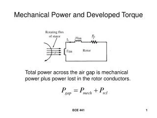
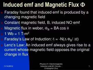
SEE 3433 ELECTRICAL MACHINES. Induced emf Developed torque Magnetization curve. + e a . v. Induced emf. Regardless of operation, emf is always induced in armature circuit when there is rotation.

E N D
SEE 3433 ELECTRICAL MACHINES Induced emf Developed torque Magnetization curve
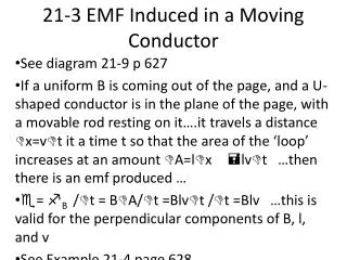
+ ea v Induced emf Regardless of operation, emf is always induced in armature circuit when there is rotation For a conductor of length l, moving at a speed v in magnetic field intensity B, the induced voltage is given by: X X X X X X X X X X X X X X X X X X X X X X X X X X X X X X X X ea= B v l Induced emf ea= Bv l
_ + + _ + ea + ea ea= 2 B m r l In terms of flux per pole, where = B A and Induced emf l
Induced emf where = B A and which gives This is an induced voltage for a single turn. If there are N turns with a parallel path,
F i Developed torque For a conductor of length l, carrying current i in magnetic field intensity B, the torque developed is given by: Fc= B i l X X X X X X X X X X X X X X X X X X X X X X X X X X X X X X X X Force produced, F = Bl i
x l i i Developed torque
Tc = B l Ia r x Tc = B l Ia r In terms of flux per pole, where = B A and Developed torque T = F r l Ia Ia T2c = 2 B l Ia r
Developed torque This is torque for a single turn. If there are N turns with a parallel path, Similar to the constant obtained in induced emf !
+ Ea If Field current (flux per pole) depends on field (stator) current and hence MMF of the stator circuit - angular speed of the rotor K is a constant – depends on physical construction of the machine Magnetization curve Is a plot of the induced emf vs If on an open armature circuit, at a given rotor speed Armature circuit Field circuit Induced emf Ea= K At a given speed and K, the emf induced depends on
If Magnetization curve How does vary with the field current? Flux will increase with field current - but not necessarily linear! Flux path produced by field: stator core air gap rotor core airgap stator core At low , core reluctance is small – most of MMF drop appear across air gap – consequently relation between and field current is almost linear (due to the airgap)
If Magnetization curve How does vary with the field current? As field current increases, so too - some part of the core (especially the rotor teeth) will saturate Relation between and Ifield is no longer linear
Ea 2 Reduced speed 3 Ifield Magnetization curve 1 1 > 2 > 3 Since for constant speed Ea the curve can be represented by Ea vs If