Download
1 / 26
260 likes | 420 Vues
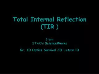
Fibre Optics. Introduction. 1870 Tyndall demonstrated that light can be guided along a curved stream of water Why? Total internal reflection Electronic communication use radio and microwaves to carry information copper wires and co-axial cables

E N D
Fibre Optics Introduction
1870 Tyndall demonstrated that light can be guided along a curved stream of water Why? Total internal reflection Electronic communication use radio and microwaves to carry information copper wires and co-axial cables (Limited band width, information carrying capacity is less)
Use of optical fibre in place of wires enhances the number of signals that can be transmitted simultaneously 1960: Light could be guided by a glass fibre High Attenuation 1970: Invention of solid state laser, made optical communication practicable 1977: Commercial communication systems based on optical fibres made their appearance Optical fibres also used in Fibroscopes, useful in medical diagnostics
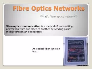
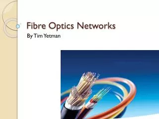
An optical fibre is a transparent conduit as thin as human hair made of glass or clear plastic, made to guide light waves along its length Optical Fiber
Practical optical fibre has three co-axial regions 1. Core- Light guiding region 2. Cladding- Co-axial middle region 3. Sheath- Increases mechanical strength of fibre The refractive index of cladding is always lower than that of the core Why? Purpose of cladding to confine the light to core, How?
All the rays having ray directions less than the critical angle will be trapped in the fibre due to total internal reflection Only certain ray directions are allowed to propagate Modes of the fibre: possible number of paths of light in the fibre
Acceptance angle is the maximum angle that a light ray can have relative to the axis of the fibre and can propagate down the fibre Fractional Refractive Index Change Fractional refractive index change should be very less than 1 for effective guide of light; of the order of 0.01
Numerical Aperture The light gathering ability of a fibre depends on two factors, Core Size and the Numerical Aperture The acceptance angle and fractional refractive index change determine the NA of the fibre, NA does not depend on the physical dimensions of the fibre NA = sin , i.e. The numerical aperture is defined as the sine of the acceptance angle
Types of Optical Fibres Single Mode Fibre: Single mode step index fibre Multimode Fibre: Multimode step index fibre Multimode Graded index fibre
Single Mode Step Index Fibre: Refractive index changes abruptly at the core-cladding boundary. Light travels along a single path i.e. along the axis. This fibre has low value of NA and Intermodal dispersion does not exist (only one mode exist). With careful choice of material, dimension and wavelength dispersion can be made extremely small. Low dispersion makes it suitable for use with high data rates. Fibre is costly Multimode Step Index Fibre: Its core has larger diameter than SMF. It has higher dispersion, i.e. less efficient transmission. Easy to manufacture and less costly. Graded Index (GRIN) Fibre: Multimode fibre with a core consisting of concentric layers of different refractive indices. It has higher value at the centre and falls of with increasing radial distance from the axis. Numerical aperture and acceptance angle decreases with radial distance. Number of modes is half than the similar MMF. Less dispersion, manufacturing is more complex
Pulse Dispersion: Pulse-broadening effect by fibres The pulse that appears at the output of the fibre is wider than the input pulse. Dispersion is measured in units of time, typically nanoseconds and picoseconds Intermodal Dispersion
It is dispersion between the modes, caused by the difference in propagation time for the different modes. Numerous modes traveling in a fibre travel with different velocities with respect to the fibre axis, leading to a spread of the input pulse. Intramodal Dispersion: Light in a fibre consists of a group of wavelength. Light of different wavelength travels at different speeds in a medium. A narrow pulse tend to broaden as they travel down the fiber Waveguide Dispersion: It arises due to guiding property of fibre. The refractive index of any mode changes with wavelength, causes pulse spreading Large NA- More modes, more dispersion
Attenuation Signal attenuation is defined as ratio of the optical output power from a fibre of length L to the input optical power, in case of an ideal fibre the attenuation would be zero 1. Absorption by material 2. Scattering 3. Waveguide and microbend loss
Applications 1. Illumination and Image Transmission: Endoscopes 2. Optical Communications: light signals replace the traditional electric signals. Increased bandwidth is achieved 3. Optical Fibre Sensors: The variation of refractive index of the optical fibre under the influence of external forses is utilized in fabrication of optical fibre sensors Thermometer: LED, Coil of fibre optic and photo-detector Smoke and Pollution Detector Liquid Level Sensor: Useful in filing of petrol tanks 4. Medical Applications: Endoscopes, in Ophthalmology, in Cardiology, treatment of cancer 5. Military Applications: An aircraft, a ship or a tank requires tons of copper wire for communication, that can be reduced by optical fibre. Fibre guided missiles are used in recent wars
Fibre Optics Communication System Very much similar to a traditional communications system Transmitter: Converts electrical signal to light signals Optical fibre: Transmits the signals Receiver: Captures the signals at the other end of the fibre and converts them to electrical signals
Advantages 1. Cheaper 2. Smaller in size, lighter in weight, flexible yet strong 3. Not hazardous 4. Immune to EMI and RFI 5. No cross talk 6. Wider bandwidth 7. Low loss per unit length