Download
1 / 29
290 likes | 536 Vues
The Static Analysis Model Class Diagrams. Prof. Hany H. Ammar, CSEE, WVU, and Dept. of Computer Science, Faculty of Computers and Information, Cairo University. outline. UML Development, the Requirements Model and the Analysis model The Static Analysis Model – The Analysis Process

E N D
The Static Analysis ModelClass Diagrams Prof. Hany H. Ammar, CSEE, WVU, and Dept. of Computer Science, Faculty of Computers and Information, Cairo University
outline • UML Development, the Requirements Model and the Analysis model • The Static Analysis Model – The Analysis Process • The Conceptual Level - Identifying the Classes of Objects • The Analysis Level – Identifying Class relationships, class attributes, and class operations
SCENARIOS ACTORS USE CASES UML Development - Overview REQUIREMENTS ELICITATION Time D REQUIREMENTS Engineering A SEQUENCE DIAGRAMS T A ANALYSIS CLASS DIAGRAM(S) StateChart DIAGRAMs ANALYSIS Specify Domain Objects D I OPERATION CONTRACTS C T Architectural Design Include Design Objects I SUBSYSTEM CLASS/ OR COMPONENT DIAGRAMS DESIGN SEQUENCE DIAG. DEPLOYMENT DIAGRAM O N Design DESIGN DIAGRAMS A R Detailed DESIGN Y Object Design IMPLEMENTATION CHOICES IMPLEMENTATION Activity DIAGRAMS IMPLEMENTATION PROGRAM
The Requirements Model and the Analysis Model Requirements Elicitation Process Functional/ Nonfunctional Requirements Use Case Diagrams/ Sequence Diagrams (the system level) The Analysis Process Static Analysis Dynamic Analysis - Class Diagrams - State Diagrams/ Refined Sequence Diagrams (The object level)
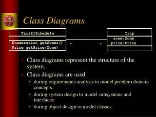
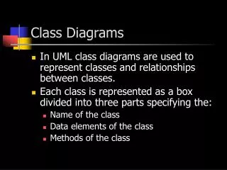
Static ModelingClass Diagrams A Class is defined as –Real world entity type about which information is stored –Represents a collection of identical objects (instances)–Described by means of attributes (data items) –Has operations to access data maintained by objects –Each object instance can be uniquely identified Relationships between classes –Associations –Composition / Aggregation –Generalization / Specialization
The Static Model • Defines the static structure of the logical model • Represents classes, class hierarchies using packages, classes, and their relationships, • Evolve in three phases the conceptual phase, the analysis phase, and the design phase.
The conceptual Level • At the conceptual phase, classes are defined based on the classes found in the problem domain descriptions (based on the objects identified in step 6 in the Requirements Elicitation Process) • A context class diagram is defined first, where the system under development is represented by one package, and other classes represent external classes representing the actors
Context Class DiagramDefines the Boundary of the system <<external>> Input Devices <<external>> Output Devices System under development <<external>> Other Actors Specify the classes of the external input/output devices and other actors (users, other systems, etc.) and the system classes See Vending Machine example in slides 5 slides no. 19-20
The conceptual Level • The system package is defined by a diagram representing the main classes and interface classes to external classes • Each subsystem is represented by a class diagram defining the classes of objects needed to realize the use cases defined in the use case diagrams
The conceptual Level Identify the system classes as Interface objects, Monitors objects, controllers objects, <<Interface>> Input_devices or actors Monitors Controllers <<Interface>> Output_devices or actors
Example of System packages of E-Commerce Application 3 types of classes: Boundary, entity, and control See text p.177 Boundary control control Boundary control entity entity
The Analysis Level • At the analysis level, class diagrams are refined by adding relationships between classes, attributes and methodsdepicting how objects of the static view are used to realize use cases in sequence diagrams • Emphasis is placed on distributing behavior, resolving software interfaces, and identifying generalization relationships that will maximize the effectiveness of the object model
The Class Diagram Notation • Identify classes, attributes of each class, and operations of each class • Classes, their attributes and methods are specified based on the objects needed to realized use case and interfaces to external entities (see slides 3, registration system example: slides 26-43) Detailed Attributes, Data types, And operations Are defined/ refined During design
Identify Class relationships Pilot Commands Aircraft Control Parent Association Child Aggregate/ Whole Aggregated/ Part Generalization Aggregation (hollow diamond)/ Composition (solid diamond)
Associations Between Classes • Associations between classes are generally shown as solid lines connecting the associated classes. • A notable exceptions to the solid line rule are the use of dashed lines to depict dependencies as special case of association,
Associations • Association is –static, structural relationship between classes –E.g, Employee works in Department • Multiplicity of Associations • Specifies how many instances of one class may relate to a single association, Company hasPresident • 1-to-many association,Bank managesAccount • Optional association (0, 1, or many) –Customer ownsCredit Card instance of another class • 1-to-1 • Many-to-Many association –Course has Student, and Student attends Course
Dependency: A Special Case of Association Dependency Client CommandManager (Client class) depends on services provided by the other three server classes
Aggregation Relation • Aggregation – A hollow diamond is attached to the end of the path to indicate aggregation. The diamond is attached to the class that is the aggregate. Aggregation provides a definitive conceptual whole part relationship
Aggregation Example Zero or more of Is an aggregate of Explore other examples of Aggregation
Composition: A Special Case of Aggregation Composition is shown as a solid filled diamond, with the diamond attached to the class that is the composite. Composition is a form of aggregation that requires coincident lifetime of the part with the whole and singular ownership; i.e. the part is owned by only one whole and is deleted when the whole is deleted Is composed of
Generalization/Specialization Relation • Generalization is shown as a solid-line arrow from the child (the more specific element) to the parent (the more general elementthis type of relationship is also called inheritance. • Should be used to define class hierarchies based on abstraction
Generalization/Specialization Relation • Controllers and Monitors are examples of abstract classes Controller Brake Controller Engine Controller
Example of identifying Class Relations, Multiplicities, Attributes and operations
Example of Software Architecture Using UML2 • SATELLITE CONTROL SYSTEM Architecture
A Simple Example of Software Architecture Using UML2 • SATELLITE CONTROL SYSTEM Architecture