Download
1 / 20
200 likes | 326 Vues
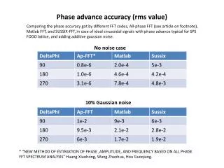
Real-Time Phase-Stamp Range Finder with Improved Accuracy. Akira Kimachi Osaka Electro-Communication University Neyagawa, Osaka 572-8530, Japan. Outline. Introduction Phase-stamp range finder (PSRF) Time-domain correlation image sensor (CIS) Phase-stamp imaging (PSI) Problem of artifacts

E N D
Real-Time Phase-Stamp Range Finder with Improved Accuracy Akira Kimachi Osaka Electro-Communication University Neyagawa, Osaka 572-8530, Japan Optical Engineering + Applications, San Diego Convention Center
Outline • Introduction • Phase-stamp range finder (PSRF) • Time-domain correlation image sensor (CIS) • Phase-stamp imaging (PSI) • Problem of artifacts • Accuracy improvement by calibrating the CIS for PSI • Experiment #1: CIS output behavior in PSI • CIS output model for PSI • Compensation for phase stamp errors • Experiment #2: accuracy evaluation • Conclusions
Real-time range imaging • Demands • Assembly/inspection of industrial products • Environment recognition for robots/vehicles • Observation of mobile objects • Assistance in human workspace • Active vs. passive range finders • Active methods are preferable in terms of accuracy/reliability
Real-time active range finders • Robustness vs. depth resolution • Difficult to establish both
Objective • Phase-stamp range finder (PSRF) Kimachi and Ando, Electronic Imaging (2007) • Time-domain correlation image sensor (CIS) • Frame-rate 3D capture based on “phase stamp” imaging (PSI) • Problem of artifacts • Solution • Analyze the behavior of CIS outputs in PSI • Model the CIS outputs for PSI • Calibrate the PSRF by compensating for CIS output errors undulation ~ 3.5 mm rms random noise pattern ~ 1 mm rms flat board @ 400 mm
Correlation image sensor (CIS) Ando and Kimachi, Trans. IEEE ED (2003) 200x200-pixel CMOS camera Output images : frame integral Temporal correlation Average intensity
Phase-stamp imaging (PSI) Higher temporal resolution than the frame period uncorrelated frame Correlation images noise Phase stamp image Light pulse energy image
Phase-stamp range finder (PSRF) surface reflectance • One SOL scan in one frame • Based on PSI SOL angle (SOL) ambient illumination SOL energy • Range image from single frame • Ambient illumination removed • Surface reflectane canceled Phase stamp Incident light intensity Correlation images Reference signals : pixel spacing in x Range image Kimachi and Ando, Electronic Imaging (2007)
PSRF artifacts +p/2 • Artifacts in range images • Undulation • Random noise pattern • Considered to be caused by errors in detected phase stamps • Temporal correlations may not follow the ideal characteristics with respect to SOL incidence time p 0 -p/2 average intensity SOL energy phase stamp range map (flat board @ 400 mm)
Investigating CIS outputs in PSI • Capture a sequence of correlation images while shifting pulse occurrence time
Results: image average behavior Image averages of temporal correlations increase monotonically with , , and Undulations in the phase stamp become severer as increases Distortions in from sine functions become severer as increases Pulse height varied Amplitude varied Pulse width varied
oscillate with in arbitrary waveforms, randomly with respect to pixel and channel Results: pixel-wise deviation behavior +p/2 p 0 -p/2 Pixel-wise deviations of temporal correlations increase monotonically as , , and Pixel-wise deviations of computed phase stamps oscillate with Pulse height varied Amplitude varied Pulse width varied
CIS output model for PSI • Ideal characteristic of CIS temporal correlation outputs • Experiment-based CIS output model for PSI • Undulation/distortion→ Harmonics , , • Pixel-/channel-wise random deviation→ Coefficients , , , , • Dependence on light pulse energy → Multiplication by • Coefficients are estimated from a sequence of PSI images by least-squares fitting (for fixed ) noise
Compensation for phase stamp errors For a single-frame set of temporal correlation images , , and , • Compute the phase stamps • Approximate the PSI CIS model by regarding as containing a small error • Estimate and pixel-wise by least-squares fitting to the model with and the pre-estimated coefficients , , , , • Obtain the phase stamp estimates
Results: CIS calibration for PSI (1) test data = calibration data • Fitting — over a sequence of • Compensation — on a single frame of
Results: CIS calibration for PSI (2) test data = calibration data test data ≠ calibration data
Results: CIS calibration in PSI (3) Before compensation After compensation test data ≠ calibration data
Results: artifacts removal in PSRF flat board @ 400 mm uncompensated compensated SOL intensity phase stamp paper box can bottle
Conclusions • Artifacts in PSRF outputs have been removed • CIS outputs were modeled based on PSI experiments • A method for compensating for phase stamp errors in CIS outputs was proposed • Confirmed in experiments • Accuracy improved on a PSRF system • Undulation — 3.45 mm → 0.48 mm • Random noise pattern — 1.09 mm → 0.55 mm