Download
1 / 3
30 likes | 166 Vues
ECE 320 Homework #4. Using 8 data input selector logic (MUX), implement the following two functions: F(A,B,C)=S 0 S 2 S 3 S 5 F(A,B,C,D)=P 0 +P 1 +P 5 +P 7 +P 8 +P 10 +P 14 +P 15 Using 3/8 binary decoder, implement the following function: F(A,B,C)=P 0 +P 2 +P 3 +P 5

E N D
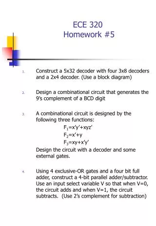
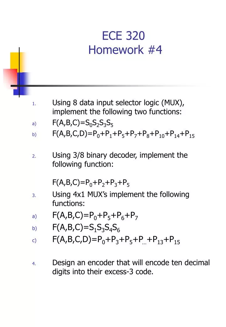
ECE 320 Homework #4 • Using 8 data input selector logic (MUX), implement the following two functions: • F(A,B,C)=S0S2S3S5 • F(A,B,C,D)=P0+P1+P5+P7+P8+P10+P14+P15 • Using 3/8 binary decoder, implement the following function: F(A,B,C)=P0+P2+P3+P5 • Using 4x1 MUX’s implement the following functions: • F(A,B,C)=P0+P5+P6+P7 • F(A,B,C)=S1S3S4S6 • F(A,B,C,D)=P0+P3+P5+P…+P13+P15 • Design an encoder that will encode ten decimal digits into their excess-3 code.
ECE 320 Homework #4 • Design the full adder/subtractor shown in Figure below. There are four inputs (Ai, Bi, CBi and F) and two outputs (SD and CB0). The input F is a control signal such that when F=0 the circuit works as a full adder: Ai and Bi represent the two bits to be added. Cbi represents the input carry. SD represents the output sum. CB0 represents the output carry and when F=1 the circuit works as a full subtractor and: Ai and Bi represent the two binary bits to be subtracted. CBi represents the input borrow. SD represents the output difference. CB0 represents the output borrow. Implement the circuit using the minimum number of gates.
ECE 320 Homework #4 Ai Bi F CBi CB0 Adder/Subtractor SD