Download

1 / 32
1.59k likes | 5.5k Vues
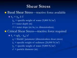
Direct Shear Test. CEP 701 PG Lab. . failure envelope. Friction angle. Cohesion. f. c. . . Mohr-Coulomb Failure Criterion ( in terms of total stresses ). . f is the maximum shear stress the soil can take without failure, under normal stress of . . ’. failure envelope.

E N D
Direct Shear Test CEP 701 PG Lab
failure envelope Friction angle Cohesion f c Mohr-Coulomb Failure Criterion(in terms of total stresses) f is the maximum shear stress the soil can take without failure, under normal stress of .
’ failure envelope Effective cohesion Effective friction angle f c’ ’ ’ Mohr-Coulomb Failure Criterion(in terms of effective stresses) u = pore water pressure f is the maximum shear stress the soil can take without failure, under normal effective stress of ’.
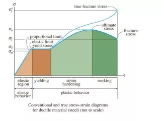
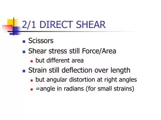
f ’f tan ’ frictional component ’ cohesive component c’ c’ ’f ' Mohr-Coulomb Failure Criterion Shear strength consists of two components: cohesive and frictional.
Normal stresses and shear stresses on any plane can be obtained with the following equations
s’1 s’ s’3 s’3 t q s’1 Soil element Mohr Circle of stress Resolving forces insandtdirections,
t s’ Mohr Circle of stress
t (s’, t) q s’ PD = Pole w.r.t. plane Mohr Circle of stress
Failure surface Y Y X X Soil elements at different locations X ~ failure Y ~ stable Mohr Circles & Failure Envelope ’
Direct shear test • NEED AND SCOPE • In many engineering problems such as • design of foundation, • retaining walls, • slab bridges, • pipes, • sheet piling, • The value of the angle of internal friction and cohesion of the soil involved are required for the design. • Direct shear test is used to predict these parameters quickly.
Direct shear test • This test is performed to determine the consolidated - drained shear strength of a sandy to silty soil. • The shear strength is one of the most important engineering properties of a soil, because it is required whenever a structure is dependent on the soil’s shearing resistance. • The shear strength is needed for engineering situations such as determining the stability of slopes or cuts, finding the bearing capacity for foundations, and calculating the pressure exerted by a soil on a retaining wall.
Apparatus • 1. Direct shear box apparatus • 2. Loading frame (motor attached). • 3. Dial gauge. • 4. Proving ring. • 5. Tamper. • 6. Straight edge. • 7. Balance to weigh upto 200 mg. • 8. Aluminum container. • 9. Spatula.
PROCEDURE • Check the inner dimension of the soil container. • Put the parts of the soil container together. • Calculate the volume of the container. Weigh the container. • Place the soil in smooth layers (approximately 10 mm thick). If a dense sample is desired tamp the soil. • Weigh the soil container, the difference of these two is the weight of the soil. Calculate the density of the soil. • Make the surface of the soil plane. • Put the upper grating on stone and loading block on top of soil.
Porous plates Components of the shear box Preparation of a sand specimen Direct shear test Direct shear test is most suitable for consolidated drained tests specially on granular soils (e.g.: sand) or stiff clays Preparation of a sand specimen
Pressure plate Leveling the top surface of specimen Specimen preparation completed Direct shear test Preparation of a sand specimen
Steel ball P Pressure plate Porous plates S Proving ring to measure shear force Step 1: Apply a vertical load to the specimen and wait for consolidation Direct shear test Test procedure
Steel ball P Test procedure Pressure plate Porous plates S Proving ring to measure shear force Step 1: Apply a vertical load to the specimen and wait for consolidation Direct shear test Step 2: Lower box is subjected to a horizontal displacement at a constant rate
PROCEDURE • Measure the thickness of soil specimen. • Apply the desired normal load. • Remove the shear pin. • Attach the dial gauge which measures the change of volume. • Record the initial reading of the dial gauge and calibration values. • Before proceeding to test check all adjustments to see that there is no connection between two parts except sand/soil. • Start the motor. Take the reading of the shear force and record the reading. • Take volume change readings till failure. • Add 5 kg normal stress 0.5 kg/cm2 and continue the experiment till failure • Record carefully all the readings. Set the dial gauges zero, before starting the experiment
Dial gauge to measure vertical displacement Shear box Proving ring to measure shear force Loading frame to apply vertical load Dial gauge to measure horizontal displacement Direct shear test
Direct shear test Analysis of test results Note: Cross-sectional area of the sample changes with the horizontal displacement
Shear stress, t Dense sand/ OC clay tf Loose sand/ NC clay tf Shear displacement Expansion Dense sand/OC Clay Change in height of the sample Shear displacement Loose sand/NC Clay Compression Direct shear tests on sands Stress-strain relationship
Shear stress, t Normal stress = s3 Normal stress = s2 Shear displacement Normal stress = s1 tf2 tf1 tf3 Shear stress at failure, tf Mohr – Coulomb failure envelope f Normal stress, s Direct shear tests on sands How to determine strength parameters c and f
Some important facts on strength parameters c and f of sand Direct shear tests on sands Direct shear tests are drained and pore water pressures are dissipated, hence u = 0 Sand is cohesionless hence c = 0 Therefore, f’ = f and c’ = c = 0
Overconsolidated clay (c’ ≠ 0) Shear stress at failure, tf Normally consolidated clay (c’ = 0) f’ Normal force, s Direct shear tests on clays In case of clay, horizontal displacement should be applied at a very slow rate to allow dissipation of pore water pressure (therefore, one test would take several days to finish) Failure envelopes for clay from drained direct shear tests
Where, ca = adhesion, d = angle of internal friction Interface tests on direct shear apparatus In many foundation design problems and retaining wall problems, it is required to determine the angle of internal friction between soil and the structural material (concrete, steel or wood)
Advantages of direct shear apparatus • Due to the smaller thickness of the sample, rapid drainage can be achieved • Can be used to determine interface strength parameters • Clay samples can be oriented along the plane of weakness or an identified failure plane Disadvantages of direct shear apparatus • Failure occurs along a predetermined failure plane • Area of the sliding surface changes as the test progresses • Non-uniform distribution of shear stress along the failure surface