Download
1 / 19
210 likes | 539 Vues
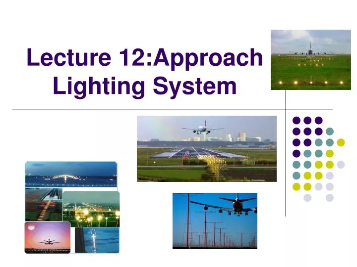
Lecture 12:Approach Lighting System. Introduction. Approach Lighting System (ALS) is the tail end of the Air Navigation System. It is a lighting systems installed on the Approach end of an Airport. ALS consist of a series of Light bars and Strobe lights. ALS uses.

E N D
Introduction • Approach Lighting System (ALS) is the tail end of the Air Navigation System. • It is a lighting systems installed on the Approach end of an Airport. • ALS consist of a series of Light bars and Strobe lights
ALS uses • ALS serve the runway that has the Instrument Approach Procedure such as Instrument Landing System (ILS). • ALS allows the pilot to see and identify the Runway end and align the aircraft to land on the runway. • At the point where Decision Height is reached, pilot must be able to see ALS, then pilot can continue the approach.
ALS uses • If pilot can not see the ALS, the approach must be aborted and a missed approach procedure will be performed. • This is where the aircraft will climb back to a predetermined altitude and position. • From there the pilot will either try the same approach again, try a different approach or divert to another airport.
ALS Configurations • ALS are designed to allow the pilot to quickly and positively identify visibility distances under Instrument Flight Rules (IFR). • The most common approach light system configurations include: • ALSF-1: Approach Lighting System with Sequenced Flashing Lights configuration 1 • ALSF-A2: Approach Lighting System with Sequenced Flashing Lights configuration 2
Approach Lighting System Configuration 2 • Used on Category II runways during instrument landing approach to align the aircraft with the centerline of the runway and to establish vertical orientation. • Up to 174 steady burning white lights serve as a reference plane, • Two rows of red side row increase the pilots horizontal perception. • Up to twenty-one white lights create a sequential strobing flash pattern that rolls toward the runway threshold. • Three intensity settings allow the approach to be used under changing weather conditions.
Importance of Approach Lighting System • As Approach Lighting System (ALS) is the tail end of the Air Navigation System, it is important to affect the aircraft landing. • ALS allows the pilot to see and identify the Runway end and align the aircraft to land on the runway. • It very important especially during night time, bad weather and poor visibility • ALS also important to verify positive contact and let you know where the begin an end of the runway is.
Visual Approach Slope Indicators (VASI) Function: To assist pilot with visual guidance during an aircraft landing by indicate the pilot’s right angle of approach.
Visual approach slope indicator • VASI are light systems to let you know your position in relation to the desired glide path in landing to the runway. • They are located on the side of the runway and can be used both during the day and at night.
Visual Approach Slope Indicators (VASI) • VASI may have 2 bars (rows) of lights. • A 2-bar system has one near and one far bar. Each bar can contain 2 light units. • If both bars show white lights, you are too high for your landing. • If both bars show red, you are too low. • If the far bar is red and the near bar is white you are just right (be on the glide path).
Precision Approach Path Indicator (PAPI) • PAPI work in a similar manner to the VASI. • The difference is PAPI only have one row of lights. • This one row contain 4 light units. • If all four lights show white, you are too high for your landing. • If all four lights show red, you are too low. • If two lights show red and two lights show white you are just right (be on the glide path).