Download
1 / 31
310 likes | 327 Vues
This article covers the services provided by the data link layer, including error detection and correction, multiple access protocols, LANs, addressing, ARP, Ethernet, switches, and VLANs.

E N D
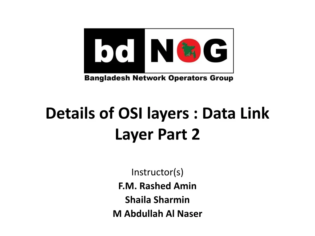
Details of OSI layers : Data Link Layer Part 2 Instructor(s) F.M. Rashed Amin Shaila Sharmin M Abdullah Al Naser
Services • Error detection, correction • Multiple access protocols • LANs • addressing, ARP • Ethernet • switches • VLANS Outline www.bdnog.org
The main tasks of the data link layer are: • Transfer data from the network layer of one machine to the network layer of another machine using hop by hop transmission over single links (single segments). • Convert the raw bit stream of the physical layer into groups of bits (“frames”) and vice versa Data Link Layer : Services Datagram Frame Electrical and Optical signals www.bdnog.org
Framing, link access: • encapsulate datagram into frame, adding header, trailer • channel access if shared medium • “MAC” addresses used in frame headers to identify source, dest • different from IP address! • Reliable delivery between adjacent nodes • seldom used on low bit-error link (fiber, some twisted pair) • wireless links: high error rates • Error control : • Error detection & Error correction Link layer services www.bdnog.org
LAN switching : • including MAC filtering, Spanning Tree Protocol (STP) and Shortest Path Bridging (SPB) • Flow control: • pacing between adjacent sending and receiving nodes • Transmission - half-duplex and full-duplex • half duplex - nodes at both ends of link can transmit, but not at same time • full duplex – nodes can transmit in both directions at the same time Link layer services (more) www.bdnog.org
Data can be corrupted during transmission. • In a single-bit error, only 1 bit in the data unit has changed. • A burst error means that 2 or more bits in the data unit have changed. • To detect or correct errors, we need to send extra (redundant) bits with data. • If the values do not match, an error has occurred. Error Detection Burst error of length 8 Single-bit error www.bdnog.org
Error correction done in two different ways: • Forward error correction (FEC): The sender encodes the data using an error-correcting code (ECC) prior to transmission. redundancy added by the code is used by the receiver to recover the original data. • Automatic repeat request (ARQ): Also called retransmission. Every block of data received is checked using the error detection code used, and if the check fails, retransmission of the data is requested . • Error-correcting coding schemes: • Convolutional codes • Block codes Error Correction www.bdnog.org
32/128-bit IP address: network-layer address for interface used for layer 3 (network layer) forwarding MAC (or LAN or physical or Ethernet) address: function: used ‘locally” to get frame from one interface to another physically-connected interface (same network, in IP-addressing sense) 48 bit MAC address (for most LANs) burned in NIC ROM, also sometimes software settable e.g.: 1A-2F-BB-76-09-AD Addresses and ARP hexadecimal (base 16) notation (each “number” represents 4 bits) www.bdnog.org
each adapter on LAN has unique MAC address LAN addresses and ARP 1A-2F-BB-76-09-AD LAN (wired or wireless) adapter 71-65-F7-2B-08-53 58-23-D7-FA-20-B0 0C-C4-11-6F-E3-98 www.bdnog.org
MAC address allocation administered by IEEE • manufacturer buys portion of MAC address space (to assure uniqueness) • analogy: • MAC address: like Social Security Number • IP address: like postal address • MAC flat address ➜ portability • can move LAN card from one LAN to another • IP hierarchical address not portable • address depends on IP subnet to which node is attached LAN addresses (more) www.bdnog.org
Question: how to determine interface’s MAC address, knowing its IP address? ARP table:each IP node (host, router) on LAN has table • IP/MAC address mappings for some LAN nodes: < IP address; MAC address; TTL> • TTL (Time To Live): time after which address mapping will be forgotten (typically 20 min) ARP: address resolution protocol 137.196.7.78 1A-2F-BB-76-09-AD 137.196.7.23 137.196.7.14 LAN 71-65-F7-2B-08-53 58-23-D7-FA-20-B0 0C-C4-11-6F-E3-98 137.196.7.88 www.bdnog.org
bus: popular through mid 90s • all nodes in same collision domain (can collide with each other) star: prevails today • activeswitchin center • each “spoke” runs a (separate) Ethernet protocol (nodes do not collide with each other) Ethernet: physical topology switch star bus: coaxial cable www.bdnog.org
sending adapter encapsulates IP datagram (or other network layer protocol packet) in Ethernet frame preamble: used to synchronize receiver, sender clock rates, mark a new incoming frame. Ethernet frame structure type dest. address source address data (payload) CRC preamble www.bdnog.org
Addresses: 6 byte source, destination MAC addresses • if adapter receives frame with matching destination address, or with broadcast address (e.g. ARP packet), it passes data in frame to network layer protocol. • otherwise, adapter discards frame. • type: indicates higher layer protocol (mostly IP but others possible, e.g., Novell IPX, AppleTalk) • CRC: cyclic redundancy check at receiver • error detected: frame is dropped Ethernet frame structure (more) type dest. address source address data (payload) CRC preamble www.bdnog.org
connectionless: no handshaking between sending and receiving NICs • unreliable: receiving NIC doesnt send acks or nacks to sending NIC • data in dropped frames recovered only if initial sender uses higher layer rdt (e.g., TCP), otherwise dropped data lost • Ethernet’s MAC protocol: unslotted CSMA/CD with binary backoff Ethernet: unreliable, connectionless www.bdnog.org
link-layer device: takes an active role store, forward Ethernet frames examine incoming frame’s MAC address, selectivelyforward frame to one-or-more outgoing links when frame is to be forwarded on segment, uses CSMA/CD to access segment transparent hosts are unaware of presence of switches plug-and-play, self-learning switches do not need to be configured Ethernet switch www.bdnog.org
hosts have dedicated, direct connection to switch • Ethernet protocol used on each incoming link, but no collisions; full duplex • each link is its own collision domain • switching:A-to-D and B-to-F can transmit simultaneously, without collisions A Switch: multiple simultaneous transmissions B F 1 2 6 4 5 3 E C D switch with six interfaces (1,2,3,4,5,6) www.bdnog.org
Q:how does switch know A reachable via interface 1, B reachable via interface 2? A Ethernet: physical topology B C’ • A:each switch has a switch table,each entry: • (MAC address of host, interface to reach host, time stamp) • looks like a routing table! 1 2 6 4 5 3 B’ C Q:how are entries created, maintained in switch table? • something like a routing protocol? A’ switch with six interfaces (1,2,3,4,5,6) www.bdnog.org
Source: A Dest: A’ MAC addr interface TTL 60 1 A A A’ • switchlearnswhich hosts can be reached through which interfaces • when frame received, switch “learns” location of sender: incoming LAN segment • Records sender/location pair in switch table A Switch: self-learning B C’ 1 2 6 4 5 3 B’ C A’ Switch table (initially empty) www.bdnog.org
Source: A Dest: A’ A’ A MAC addr interface TTL 60 60 4 1 A’ A A A’ A A’ A A’ A A’ A A’ A A’ • frame destination, A’, location unknown: A flood Self-learning, forwarding: example B C’ • destination A location known: 1 2 selectively send on just one link 6 4 5 3 B’ C A’ switch table (initially empty) www.bdnog.org www.bdnog.org
switches can be connected together S4 Interconnecting switches S1 S3 S2 A F I D C B H G E • Q: sending from A to G - how does S1 know to forward frame destined to F via S4 and S3? • A:self learning! (works exactly the same as in single-switch case!) www.bdnog.org
An Ethernet switchis a packet switch for Ethernet frames Buffering of frames prevents collisions Each port is isolated and builds its own collision domain AnEthernet Hubdoes not perform buffering Collisions occur if two frames arrive at the same time. Hubs vs. Switches Switch Hub 22 www.bdnog.org
Consider: CS user moves office to EE, but wants connect to CS switch? single broadcast domain: all layer-2 broadcast traffic (ARP, DHCP, unknown location of destination MAC address) must cross entire LAN security/privacy, efficiency issues. VLANs: motivation Computer Science Computer Engineering Electrical Engineering www.bdnog.org
7 1 2 8 15 9 10 16 port-based VLAN: switch ports grouped (by switch management software) so that singlephysical switch Virtual Local Area Network 15 7 9 1 VLANs 2 8 10 16 switch(es) supporting VLAN capabilities can be configured to define multiple virtualLANS over single physical LAN infrastructure. … … Computer Science (VLAN ports 9-15) Electrical Engineering (VLAN ports 1-8) … operates as multiple virtual switches … … Computer Science (VLAN ports 9-16) Electrical Engineering (VLAN ports 1-8) www.bdnog.org
forwarding between VLANS: done via routing (just as with separate switches) • in practice vendors sell combined switches plus routers router • traffic isolation: frames to/from ports 1-8 can only reach ports 1-8 • can also define VLAN based on MAC addresses of endpoints, rather than switch port Port-based VLAN 15 7 9 1 2 8 10 16 • dynamic membership: ports can be dynamically assigned among VLANs … … Computer Science (VLAN ports 9-15) Electrical Engineering (VLAN ports 1-8) www.bdnog.org
1 16 15 7 9 7 1 3 5 2 8 10 4 6 2 8 VLANS spanning multiple switches … … Computer Science (VLAN ports 9-15) Ports 2,3,5 belong to EE VLAN Ports 4,6,7,8 belong to CS VLAN Electrical Engineering (VLAN ports 1-8) • trunk port:carries frames between VLANS defined over multiple physical switches • frames forwarded within VLAN between switches can’t be vanilla 802.1 frames (must carry VLAN ID info) • 802.1q protocol adds/removed additional header fields for frames forwarded between trunk ports www.bdnog.org
type source address dest. address preamble data (payload) 802.1 frame CRC 802.1Q VLAN frame format type 802.1Q frame data (payload) CRC 2-byte Tag Protocol Identifier (value: 81-00) Recomputed CRC Tag Control Information (12 bit VLAN ID field, 3 bit priority field like IP TOS) source address dest. address preamble www.bdnog.org
Port-based VLANs use the physical port address to form the groups for the VLAN. • It is logical to connect computers that are physically close together on the LAN into ports that are physically close together on the switch, and to assign ports that are physically close together into the same VLAN. • This is the approach used in traditional LAN design: physical location determines the LAN, but is not always the most effective approach. Port-Based VLANs (Layer-1 VLANs) www.bdnog.org
Port-Based VLANs www.bdnog.org
VLAN Example www.bdnog.org