Download
1 / 49
540 likes | 828 Vues
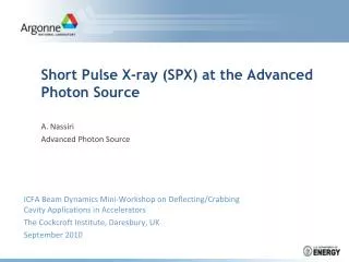
Development of superconducting undulators at the Advanced Photon Source. Yury Ivanyushenkov on behalf of the APS superconducting undulator project team Advanced Photon Source Argonne National Laboratory FNAL Accelerator Physics and Technology Seminar, September 22, 2011.

E N D
Development of superconducting undulators at the Advanced Photon Source YuryIvanyushenkov on behalf of the APS superconducting undulator project team Advanced Photon Source Argonne National Laboratory FNAL Accelerator Physics and Technology Seminar, September 22, 2011 Work supported by U.S. Department of Energy, Office of Science, Office of Basic Energy Sciences, under Contract No. DE-AC02-06CH11357.
Team Y. Ivanyushenkov (ASD) Technical Leader M. White (APS-U) Associate Project Manager Core Team Management: E. Gluskin*(ASD-MD) R. Kustom (ASD-RF) E. Moog (ASD-MD) Simulation: D. Capatina (AES-MD) R. Dejus (ASD-MD) S. Kim (ASD-MD) Design: N. Bartkowiak (AES-DD) T. Buffington (AES-DD) J. Liu (AES-MD) D. Skiadopoulos (AES-DD) E. Trakhtenberg (AES-MD) Cryogenics: J. Fuerst (ASD-MD) Q. Hasse (ASD-MD) Measurements: M. Abliz (ASD-MD) C. Doose (ASD-MD) I. Vasserman (ASD-MD) Controls: J. Xu (AES-C) Tech. support: K. Boerste (ASD-MD) M. Kasa (ASD-MD) *Group Leader Budker Institute Collaboration (Cryomodule and Measurement System Design) • N. Mezentsev • V. Syrovatin • V. Tsukanov • V. Lev Technical Support M. Borland (ASD-ADD) J. Collins (AES-MD) G. Decker* (ASD-D) B. Deriy (ASD-PS) P. Den Hartog* (AES-MD) L. Emery* (ASD-AOP) R. Farnsworth* (AES-C) J. Gagliano* (AES-VS) G. Goeppner* (AES-MOM) K. Harkay (ASD-AOP) V. Sajaev (ASD-AOP) M. Smith (AES-C) J. Penicka* (AES-SA) J. Wang* (ASD-PS) A. Zholents (ASD-DD) *Group Leader FNAL Collaboration (Impregnation) • A. Makarov UW-Madison Collaboration (Cooling System) J. Pfotenhauer D. Potratz D. Schick University of Erlangen Collaboration (Magnetic Simulation) N. Vassiljev Y. Ivanyushenkov, FNAL, September 22, 2011
Scope • Advanced Photon Source (APS) • Undulator radiation and magnetic structures • Why a superconducting-technology based undulator? • Calculated performance of superconducting undulators (SCUs) • R&D program on superconducting undulators at the APS • Heat load and cooling scheme concept • Superconducting undulator design • Magnetic field measurement system concept • SCU technology roadmap • Possible APS-FNAL collaboration on Nb3Sn undulator • Conclusions Y. Ivanyushenkov, FNAL, September 22, 2011
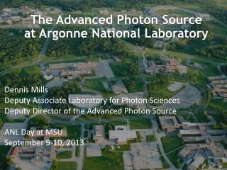
Advanced Photon Source (APS) Aerial view of the APS Y. Ivanyushenkov, FNAL, September 22, 2011
Undulator radiation Adapted from the web-site of Centre Laser Infrarouge d’Orsay: http://clio.lcp.u-psud.fr/clio_eng/FELrad.html In coordinate frame that moves with an electron in Z: Electron ‘sees’ the magnetic structure with the period length moving towards it, and emits as a dipole at the wavelength , where is the relativistic Lorentz factor. In laboratory (observer) frame: Observer sees this dipole radiation shifted to even shorter wavelength, through the relativistic Doppler effect. In the forward direction, the observed wavelength of the radiation is As a result, a 3.3-cm undulator can emit 10-keV photons on a 7-GeV electron storage ring (. Y. Ivanyushenkov, FNAL, September 22, 2011
Forms of synchrotron radiation Undulatorradiation wavelength and photon energy: Adapted from lectures by Prof. David T. Attwood, http://ast.coe.berkeley.edu/sxreuv/ Y. Ivanyushenkov, FNAL, September 22, 2011
Undulator magnetic structure Hybrid structure Permanent magnet structure Permanent magnet blocks Permanent magnet blocks Magnetic poles Magnetic field direction z z Electromagnet structure with magnetic poles Electromagnet structure -i +i +i -i z z +i -i +i -i Y. Ivanyushenkov, FNAL, September 22, 2011
APS undulator A APS hybrid Undulator A R. Dejus et al, Undulator A Magnetic Properties and Spectral Performance, ANLAPS/TB-45, 2002. Y. Ivanyushenkov, FNAL, September 22, 2011
Why a superconducting technology-based undulator ? • A superconducting undulator is an electromagnetic undulator that employs high current superconducting windings for magnetic field generation - total current in winding block is up to 10-20 kA-turns -> high peak field poles made of magnetic material enhance field further -> coil-pole structure (“super-ferric” undulator) • Superconducting technology compared to conventional pure permanent magnet or hybrid insertion devices (IDs) offers: • higher peak field for the same period length • or smaller period for the same peak field Y. Ivanyushenkov, FNAL, September 22, 2011
Peak field on axis for various insertion device technologies Comparison of the magnetic field in the undulator midplane for in-vacuum SmCo undulators (Beff) and NbTi superconducting undulators (B0) versus undulator period length for three beam stay-clear gaps. The actual undulator pole gaps were assumed to be 0.12 mm larger for the IVUs and 2.0 mm larger for the SCUs. Under these assumptions, an SCU can achieve the same field at about 2 mm larger gap than an IVU. R. Dejus, M. Jaski, and S.H. Kim, “On-Axis Brilliance and Power of In-Vacuum Undulators for The Advanced Photon Source,” MD-TN-2009-004 Y. Ivanyushenkov, FNAL, September 22, 2011
Brilliance tuning curves for various ID technologies On-axis brilliance tuning curves for three in-vacuum undulators (1.6-cm, 2.0-cm, and 2.5-cm periods, each 2.4-m long) compared to undulator A for harmonics 1, 3, and 5 in linear horizontal polarization mode for 7.0-GeV beam energy and 100-mA beam current. The minimum reachable harmonic energies were calculated assuming SmCo magnets and a 5.0-mm beam stay-clear gap. The current design values for the superconducting undulator (SCU) at 9.0-mm pole gap have been marked separately by the two Xs. The SCU at the first harmonic energy of 17.2 keV nearly overlaps with the SmCo undulator at 5.0 mm gap. Ideal magnetic fields were assumed. R. Dejus, M. Jaski, and S.H. Kim, “On-Axis Brilliance and Power of In-Vacuum Undulators for The Advanced Photon Source,” MD-TN-2009-004 Y. Ivanyushenkov, FNAL, September 22, 2011
Brilliance tuning curves for superconducting IDs On-axis brilliance tuning curves with the overlaps between harmonics removed for five superconducting undulators (1.6-cm, 2.0-cm, 2.5-cm, 3.0-cm, and 3.5-cm periods, each 2.4-m long) compared to undulator A for harmonics 1, 3, and 5 in linear horizontal polarization mode for 7.0-GeV beam energy and 100-mA beam current. The minimum reachable harmonic energies were calculated assuming a 9.0 mm magnetic pole gap. The markers (*) indicate the beginning of each harmonic tuning curve for 10.0-mm pole gap. Ideal magnetic fields were assumed. R. Dejus, M. Jaski, and S.H. Kim, “On-Axis Brilliance and Power of In-Vacuum Undulators for The Advanced Photon Source,” MD-TN-2009-004 Y. Ivanyushenkov, FNAL, September 22, 2011
Performance requirements Brightness Tuning Curves (SCUs1.6 cm vs. UA 3.3 cm vs. Revolver U2.3 cm & U2.5 cm) • Tuning curves for odd harmonics of the SCU and the “Advanced SCU” (ASCU) versus planar permanent magnet hybrid undulators for 150 mA beam current. • The SCU 1.6 cm surpasses the U2.5 cm by a factor of ~ 5.3 at 60 keV and ~ 10 at 100 keV. • The tuning range for the ASCU assumes a factor of two enhancement in the magnetic field compared to today’s value – 9.0 keV can be reached in the first harmonic instead of 18.6 keV. • Reductions due to magnetic field errors were applied the same to all undulators (estimated from one measured Undulator A at the APS.) Y. Ivanyushenkov, FNAL, September 22, 2011
Why a superconducting technology-based undulator ? • Superconducting technology-based undulators outperform all other technologies in terms of peak field and, hence, energy tunability of the radiation. • Superconducting technology opens a new yet somewhat unexplored avenue for IDs. Y. Ivanyushenkov, FNAL, September 22, 2011
Major Challenges • High field quality requirements: • low phase error (< 8 degrees r.m.s.) • low field integrals (1st field integral ≤ 100 G-cm , 2nd field integral ≤105 G-cm2) • measurement of SCU performance before installation into storage ring • Superconducting coils cooling in presence of heat load from the beam: • heat load on the beam chamber of 1-10 W/m Y. Ivanyushenkov, FNAL, September 22, 2011
Solving challenges – R&D scope Y. Ivanyushenkov, FNAL, September 22, 2011
R&D on superconducting undulator for the APS • APS superconducting undulator specifications • R&D phase of the project The R&D effort aimed at developing construction techniques for superconducting planar undulators up to 2.4 meters long intensified in 2008. This program involves: - magnetic modeling - developing manufacturing techniques - building and testing short prototype magnets - and thermal tests of possible cooling schemes. Y. Ivanyushenkov, FNAL, September 22, 2011
Current direction in coil Period • + • • + • + • + • + e- • + • + • + • + • + • pole coil Superconducting planar undulator topology Current directions in a planar undulator Planar undulator winding scheme Magnetic structure layout On-axis field in a planar undulator Cooling tube Beam chamber Y. Ivanyushenkov, FNAL, September 22, 2011
Magnetic design 3d model in Opera Y. Ivanyushenkov, FNAL, September 22, 2011
Coil fabrication R&D • Coil fabrication process: • Core manufacture (10 μm precision achieved) • Coil winding (high quality achieved) • Coil impregnation (good results achieved) First wound 42-pole test coil First five 10-pole test coils A model of test coil Y. Ivanyushenkov, FNAL, September 22, 2011
Test setup in vertical cryostat 42-pole magnetic structure Y. Ivanyushenkov, FNAL, September 22, 2011
Test setup in vertical cryostat (2) • Assembly immersed into liquid helium (LHe) in the vertical cryostat. • Level of LHe in the cryostat bore is measured with level sensor, LHe is topped up when required. • Hall probe is driven by a mechanical stage that is equipped with a position encoder outside the cryostat. • LabView is employed to control movement of the Hall probe as well as to control the 2 main power supplies . • Field profile is measured by the Hall probe every 0.1 mm (according to the encoder). • Hall probe is calibrated at cryogenic temperatures. Y. Ivanyushenkov, FNAL, September 22, 2011
Coil training • Coil A max current: 760 A, max current reached after 5 quenches • Coil B max current: 720 A, required many quenches to reach its max current Y. Ivanyushenkov, FNAL, September 22, 2011
Coil excitation • Iron is already saturated at about 150 A • Iron adds about 0.2 T to the peak field • Operating current for 25 keV – 200 A; for 20 keV – 500 A (max current 720 A) Y. Ivanyushenkov, FNAL, September 22, 2011
Measured field profile Measured RMS phase error is 1.8° at 500 A Y. Ivanyushenkov, FNAL, September 22, 2011
Short magnet R&D summary table * Original specification for Undulator A was ≤ 8◦ Y. Ivanyushenkov, FNAL, September 22, 2011
First two undulators APS superconducting undulator specifications • Tuning curves for odd harmonics for two planar 1.6-cm-period NbTi superconducting undulators (42 poles, 0.34 m long and 144 poles, 1.2 m long) versus the planar NdFeB permanent magnet hybrid undulator A (144 poles, 3.3 cm period and 2.4 m long). Reductions due to magnetic field error were applied the same to all undulators (estimated from one measured undulator A at the APS). The tuning curve ranges were conservatively estimated for the SCUs. Y. Ivanyushenkov, FNAL, September 22, 2011
Cooling system- dynamic heat load • Task for cooling system is to keep the temperature of superconductor in the range 4.2-6K by intercepting both static and dynamic heat loads in the undulator system. Dynamic heat load Y. Ivanyushenkov, FNAL, September 22, 2011
Cryocoolers 4K/60K Current lead assemblies He fill pipe 1 2 LHe vessel HTS leads He recondenser Cold mass support Cryostat vacuum vessel 20K radiation shield 60K radiation shield Beam chamber @ 20K LHe Heater RF fingers SC coils Cryocoolers 20K/60K 3 4 SCU0 cooling scheme Conceptual points: • Thermally insulate beam chamber from the rest of the system. • Cool the beam chamber separately from the superconducting coils. In this approach beam heats the beam chamber but not the SC coils! Y. Ivanyushenkov, FNAL, September 22, 2011
He fill/vent turret Cryostat vacuum vessel Cryocooler Cryocooler Current leads Beam chamber flange Cryocooler Vacuum pump Cryocooler SCU0 cryostat layout Y. Ivanyushenkov, FNAL, September 22, 2011
He fill/vent turret SC magnet LHe vessel LHe piping 20 K radiation shield 60 K radiation shield Beam chamber Beam chamber thermal link to cryocooler SCU0 cryostat structure Cryostat contains cold mass with support structure, radiation shields, cryocoolers, and current lead assemblies. SCU0 and SCU1 use the same cryostat design. Y. Ivanyushenkov, FNAL, September 22, 2011
SCU0 cryostat structure (2) Y. Ivanyushenkov, FNAL, September 22, 2011
He recondenser flange LHe vessel (StSteel/Cu bimetal ) Cold mass base frame Flexible Cu braids SC magnet Beam chamber Cu bar Flexible Cu braids Cold mass Cold mass includes SC magnet, LHe vessel with piping, and cold beam chamber with thermal links to cryocoolers. Cold mass is structurally supported by base frame. Y. Ivanyushenkov, FNAL, September 22, 2011
LHe return pipe LHe supply pipe Bellows Helicoflex connectors Ceramic inserts LHe system piping LHe flows from the LHe vessel into SC magnet cores and returns into the LHe vessel. He vapor is then recondensed into liquid in the LHe vessel. Y. Ivanyushenkov, FNAL, September 22, 2011
Cooling circuit tests Helium vessel with a model of SCU cores. Cartoon representing thermosiphon operation. Three-channel test assembly installation. Average mass flow rate as a function of horizontal heat load for single channel test. Daniel C. Potratz, “Development and Experimental Investigation of a Helium Thermosiphon”, MS Thesis, University of Wisconsin-Madison, 2011 Y. Ivanyushenkov, FNAL, September 22, 2011
SCU0 measurement strategy Guiding tube passive holder • After fabrication, SC coils are characterized in the vertical LHe bath cryostat. 2-m and 3-m cryostats are available. SCU Guiding tube active holder • Once the SCU0 undulator is assembled, the magnetic field will be measured with a horizontal measurement system containing a Hall probe assembly and rotating stretched coils. Guiding tube passive holder Rotation stage SCU Long horizontal stage Y. Ivanyushenkov, FNAL, September 22, 2011
Measurement system design concept 6529 mm Guiding tube active holder Guiding tube passive holder 2036 mm Rotation stage SCU Long horizontal stage 1400 mm This concept is developed and used by Budker Institute team for measuring their superconducting wigglers. Y. Ivanyushenkov, FNAL, September 22, 2011
Warm guiding tube concept Warm (~300K) carbon fiber tube holding Hall probe /coils Warm (~300K) ¼” OD SS or Ti guiding tube Cold (20K) Al beam chamber Y X Vacuum Air Guiding tube is heated by electrical current. Y. Ivanyushenkov, FNAL, September 22, 2011
Mechanical concept Guiding tube passive holder Rotation stage Z-stage Guiding tube active holder Carbon fiber tube X-stage X-stage Ti guiding tube X-stage Y. Ivanyushenkov, FNAL, September 22, 2011
Hall probe calibration facility at the Advanced Photon Source • The reference magnetic field of the calibration electromagnet is measured with NMR probes. • A small research liquid helium cryostat by Janis is employed to calibrate Hall sensors at temperatures between 5 K and 300 K. Two Hall sensors response normalized to room temperature Electromagnet with a set of NMR probes More details are in the talk by MelikeAbliz at the Superconducting Undulators Workshop, APS, September 20-21. http://sri2010.aps.anl.gov/program/workshop-3/presentations/mon/Abliz.pdf A custom-made Hall probe holder attached to a cold finger Janis cryostat with vacuum jacket removed Y. Ivanyushenkov, FNAL, September 22, 2011
SCU technology roadmap Feasibility study: Learn how to build and measure short superconducting magnetic structures APS Upgrade R&D phase: Build and test in the storage ring (SR) full-scale undulators SCU0 and SCU1 based on NbTi superconductor Production phase: Build and install into SR three undulators SCU2-1, SCU2-2, and SCU2-3 Beyond APS Upgrade Long term R&D : - work on Nb3Sn and HTS structures, - switchable period length, - improved cooling system, - optimized cryostat and a small-gap beam chamber to explore full potential of superconducting technology Y. Ivanyushenkov, FNAL, September 22, 2011
Superconducting undulators in the APS upgrade program The APS-Upgrade program includes delivery of a test superconducting undulator (SCU0) in the R&D phase, prototype undulator SCU1 in the Engineering Development phase plus three more user devices in the Production phase – SCU2-1, SCU2-2, and SCU2-3. * preliminary Y. Ivanyushenkov, FNAL, September 22, 2011
SCU0 schedule and status • Completed in August • Cryostat package (vacuum vessel, LHe tank and two radiation shields) is received; • magnet structure is fabricated, being tested; • many components are received. • Design is completed; • long stage is received; • components are ordered. Y. Ivanyushenkov, FNAL, September 22, 2011
SCU0 cryostat fabrication SCU0 cryostat assembly at PHPK SCU0 cryostat leak test at PHPK Y. Ivanyushenkov, FNAL, September 22, 2011
Beyond APS upgrade: Advanced SCU ASCU is an Advanced SCU with peak field increased by factor of 2 as compared to SCU. x20 • Tuning curves for odd harmonics for planar permanent magnet hybrid undulators and one superconducting undulator. • The ASCU 1.6 cm surpasses the revolver-type undulator by a factor of 20 above 100 keV ! Y. Ivanyushenkov, FNAL, September 22, 2011
Superconductor stability at high current density and low peak field Preliminary calculations based on formulae by Martin N. Wilson. Y. Ivanyushenkov, FNAL, September 22, 2011
Possible APS- FNAL collaboration on Nb3Sn undulators • FNAL: • Expertise in superconducting magnet technology • Expertise in Nb3Sn • APS: • Expertise in conventional undulators • Expertise in magnetic measurements • Increasing knowledge of SCUs + New product: Short-period Nb3Sn undulator with a record-high field Y. Ivanyushenkov, FNAL, September 22, 2011
Why a superconducting technology-based undulator? (2) • Superconducting technology-based undulators outperform all other technologies in terms of peak field and, hence, energy tunability of the radiation. • Superconducting technology opens a new avenue for IDs. • Superconducting technology allows various types of insertion devices to be made – planar, helical, quasi-periodic undulators, devices with variable polarization. • We are starting with a relatively simple technology based on NbTi superconductor. A Nb3Sn superconductor will offer higher current densities and, therefore, higher peak fields combined with increased margin in operation temperature. HTS superconductors operating at temperatures around and above 77 K will allow the use of simpler (less costly) cooling systems. Y. Ivanyushenkov, FNAL, September 22, 2011
Conclusions • Superconducting technology opens a new avenue for insertion devices. • Superconducting undulator feasibility study at the APS has achieved development of magnetic structures with high quality field. • We are building the first short superconducting undulator – SCU0, based on NbTi superconductor. • A more advanced device could be built with Nb3Sn superconductor. Y. Ivanyushenkov, FNAL, September 22, 2011