Download
1 / 12
120 likes | 264 Vues
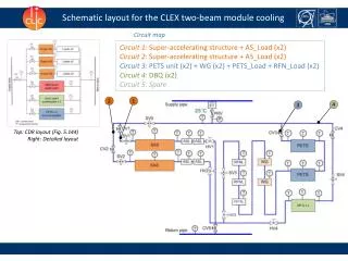
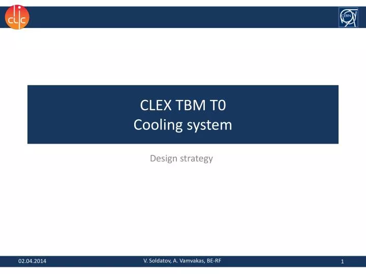
CLEX TBM T0 Cooling system. Design strategy. V. Soldatov, A. Vamvakas, BE-RF. 02.04.2014. Schematic layout for the CLEX two-beam module cooling. Phase 3.1 (see slide 9 for the RF layout). Circuit 1: Super-accelerating structure + (2x) AS_Load

E N D
CLEX TBM T0Cooling system Design strategy V. Soldatov, A. Vamvakas, BE-RF 02.04.2014
Schematic layout for the CLEX two-beam module cooling Phase 3.1 (see slide 9 for the RF layout) Circuit 1:Super-accelerating structure + (2x) AS_Load Circuit 2:PETS unit + WG + PETS_Load + RFN_Load + (2x)Idle_PETS_Load Circuit 3:(2x) DBQ 3 1 2 Top: CDR layout (Fig. 5.144) Right: Detailed layout of Phase 3.1 2
Principal components Super accelerating structure PETS (Ciemat) Drive Beam Quadrupole by Michele Modena 3
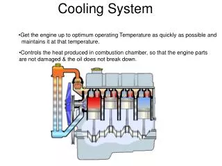
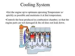
Air Heat Exchange Calculations Tamb = 20 °C Tcomp= 25 °C Η=11 W/m2/K Power generated is a fraction of what the component will dissipate to air. Therefore the water cooling system does not need to provide any additional heat dissipation and the ΔTwater=10 °C is hardly achievable.
Cooling Network of the Module • Example shows the cooling network for the CLEX T0 module with 2 SAS and 2 PETS The cooling network will consist of copper pipes (OD 8, 10 and 16mm) and standard connectors (Swagelok) Assembly Flowchart (link) Circuit 1/2 Circuit 3 5
Option 1: Independent Cooling System ~2.5 m ~12 m 3 lines in each direction CTF2 cables Coolingequipment water CLEX Return Supply Control terminal cables Shelter with electronics Cooling Rack Water chiller
Cooling Rack in CTF2 Spare SV 2 3 1 CV FT SV Spare 2 1 3 HV CV PR FT Return pipe Isometric view Supply pipe SV – Safety Valve HV – Hand Valve CV – Control valve FT – Flow Transmitter PR – Pressure Regulator
Option 2: Using of CTF3 Cooling System CLEX TBM MB Girder Main beam Girder COLD WATER 30˚C TERMOSTAT CLEX TBM DB Girder Drive beam Girder Top view CTF3 Water Supply Return (x10) CLEX TBM T0 Module Distribution manifold is connected with the equipment by means of flexible standard Kevlar pipes Supply (x10) Front view
Comparison table • Solution 1 is more sophisticated but requires complex equipment and installation. • Solution 2 has less capabilities, but is significantly simpler. • As temperature control is not possible through the water cooling system, • solution 2 is preferable.
Planning and Activities • Completion of the specification • List of equipment • Control requirements Procurement of market components • Detailed design • Cooling Rack • Module Cooling Network • Routing • Control components • Electronics and Software • Control terminal • Monitoring and control software Installation works in CTF2 and CTF3 Approval