Download
1 / 27
270 likes | 277 Vues
II. Fold Modeling. Balanced cross section. Principles of ‘ balanced ’ cross sections. The true section is retrodeformable. Any retrodeformable section is a possible model. The solution is not unique however in general.The ‘ space ’ of retrodeformable section is often large.

E N D
II. Fold Modeling • Balanced cross section
Principles of ‘balanced’ cross sections • The true section is retrodeformable. • Any retrodeformable section is a possible model. • The solution is not unique however in general.The ‘space’ of retrodeformable section is often large. • >>We need assumptions to limit possibilities: • Conservation of mass is often assumed to convert to conservation of volume (not correct in case of compaction or metamorphism). • if plane strain is assumed or if the structure is cylindrical, conservation of volume converts to conservation of area NB: Balanced = retrodeformable
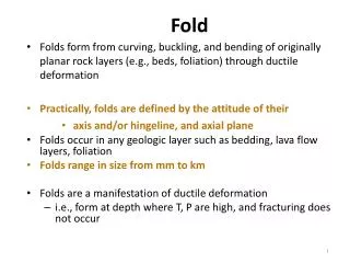
Parallel folding Parallel folds commonly form by a deformation mechanism called flexural slip, where folding is accommodated by motions on minor faults that occur along some mechanical layering -- usually bedding. Flexural-slip surfaces, which can be observed in core or outcrop, may vary in spacing from a few millimeters to several tens of meters in spacing. In that case of flexural slip folding there is conservation of bed length and of bed thickness
First define section and assemble the data. • Two popular methods can then be used to construct balanced cross sections • The Busk Method (Busk, 1929) • - The Kink Method (Holland, 1914)
The Busk’ method… parallel and concentric folds
The Kink method for a parallel fold… The kink method is based on the assumption of flexural slip folding in the limit where dip angles varie only across axial surfaces (it is equivalent to the Busk method with infinite curvature within dip domains and zero curvature within axial surface. γ γ • the axial surface bisects the angle between the fold limbs Axial angle :γ
The Kink method for a parallel fold… Holland, 1914
Constructing a balanced cross-section from the kink method • Assemble data (surface and subsurface observations) • Define dip domains, positions and dip angles of axial surface. • Extrapolate at depth by trials and errors. (you will need an eraser, experience will help). • Test that the section is indeed retrodeformable.
The Kink method for a parallel fold… • where two axial surfaces intersect, a new axial surface is formed. Its dip angle bisects the dip angles of the adjacent dip domains
The Kink method for a parallel fold… • Dip angles are constant within dip domains separated by axial surfaces. • the axial surface bisects the angle between the fold limbs
The kink method is more general than the Busk method (any curve can be divided in straight segments).
Minimum Shortening: 17.5km This section is retrodeformable and is thus a plausible model (but not a unique solution). A balanced cross-section generally yields a lower bound on the amount of shortening (because of erosion)
Constructing a balanced cross-section from the kink method • Assemble data (surface and subsurface observations) • Define dip domains, positions and dip angles of axial surface. • Extrapolate at depth by trials and errors. (you will need an eraser, experience will help). • Test that the section is indeed retrodeformable.
Two possible interpretations of structural measurements at the surface and along an exploration well. Which one is most plausible?
Two possible interpretations of structural measurements at the surface and along an exploration well. ‘Flat’ in hanging wall does not match ‘Ramp’ in footwall ‘Flat’ in hanging wall matches ‘Flat’ in footwall
- A balanced cross section might be checked from comparing hangingwall and footwall cutoff angles. - A balanced cross section might be checked and eventually retrodeformed based on the principle of conservation of area and conservation of bed length
Curvimetric Shortening & planimetric shortening Curvimetric Shortening: Sc= Lc-l Planimetric shortening: Sa=Asr/h Structural relief: Asr Undeformed depth of decollement below bed: h Area of Shortening: A Conservation of area implies: A=Asr= Sc*h. NB: Both quantities refer to a particular bed.
Curvimetric Shortening & planimetric shortening Curvimetric Shortening: Sc= Lc-l Structural relief: Asr Depth of decollement below bed: h Area of Shortening: A Conservation of area implies: A=Asr= Sc*h Planimetric shortening: A/h=Asr/h Conservation of area and bed length implies : - curvimetric shortening = planimetric shortening - Asr should increase linearly with elevation above decollement.
Sc= 0,95km Asr/h=2.6km Sc= 0,95km Asr/h=0.95km If area and bed length is preserved during folding then b is the most plausible solution …or a is correct but some diapirism is involved
Equality of curvilinear and planimetric shortening can be used to either check the section or predict the depth to the decollement. Asr= Sc*h
Structural relief: Asr Equality of curvilinear and planimetric shortening can be used to either check the section or predict the depth to the decollement.
Structural relief: Asr Equality of curvilinear and planimetric shortening can be used to either check the section or predict the depth to the decollement. NB: Be careful with the possibility of diapirism
The Move software Midland Valley Ltd. MOVE is the core product of the Move Suite providing a powerful structural modelling environment. Move provides data integration, 2D cross-section construction and 3D model building and is the base for the specialist structural modules for 2D and 3D kinematic, geomechanical, fracture and sediment modelling. 2D MOVE - removes deformation to restore the present day interpretation to its un-deformed state, adhering to line length and area balancing structural geology principles and taking into account the importance of geological time and its impact on the structure of today.
Sections across extensional systems can also be balanced with similar rules