Download
1 / 21
210 likes | 327 Vues
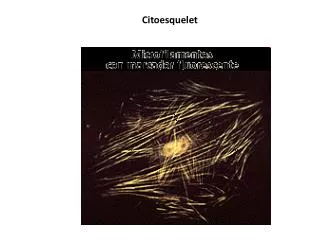
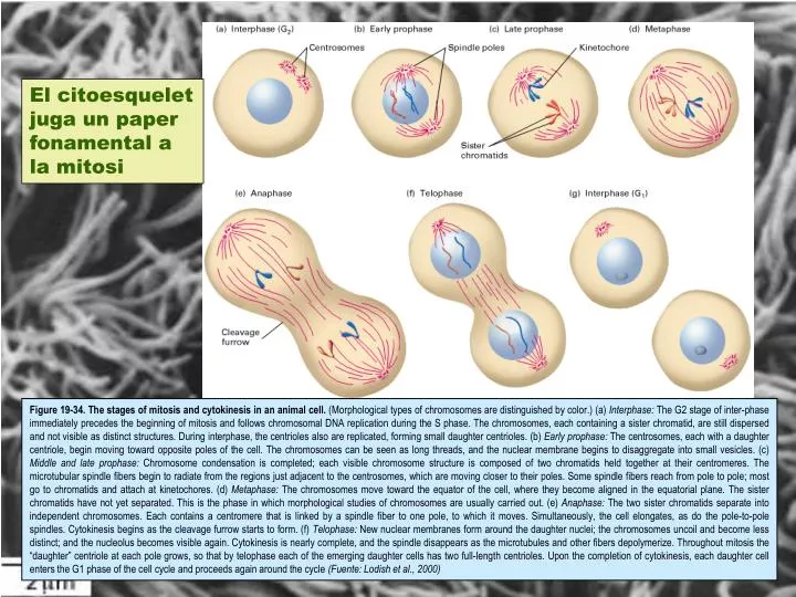
El citoesquelet juga un paper fonamental a la mitosi.

E N D
El citoesquelet juga un paper fonamental a la mitosi Figure 19-34. The stages of mitosis and cytokinesis in an animal cell. (Morphological types of chromosomes are distinguished by color.) (a) Interphase: The G2 stage of inter-phase immediately precedes the beginning of mitosis and follows chromosomal DNA replication during the S phase. The chromosomes, each containing a sister chromatid, are still dispersed and not visible as distinct structures. During interphase, the centrioles also are replicated, forming small daughter centrioles. (b) Early prophase: The centrosomes, each with a daughter centriole, begin moving toward opposite poles of the cell. The chromosomes can be seen as long threads, and the nuclear membrane begins to disaggregate into small vesicles. (c) Middle and late prophase: Chromosome condensation is completed; each visible chromosome structure is composed of two chromatids held together at their centromeres. The microtubular spindle fibers begin to radiate from the regions just adjacent to the centrosomes, which are moving closer to their poles. Some spindle fibers reach from pole to pole; most go to chromatids and attach at kinetochores. (d) Metaphase: The chromosomes move toward the equator of the cell, where they become aligned in the equatorial plane. The sister chromatids have not yet separated. This is the phase in which morphological studies of chromosomes are usually carried out. (e) Anaphase: The two sister chromatids separate into independent chromosomes. Each contains a centromere that is linked by a spindle fiber to one pole, to which it moves. Simultaneously, the cell elongates, as do the pole-to-pole spindles. Cytokinesis begins as the cleavage furrow starts to form. (f) Telophase: New nuclear membranes form around the daughter nuclei; the chromosomes uncoil and become less distinct; and the nucleolus becomes visible again. Cytokinesis is nearly complete, and the spindle disappears as the microtubules and other fibers depolymerize. Throughout mitosis the “daughter” centriole at each pole grows, so that by telophase each of the emerging daughter cells has two full-length centrioles. Upon the completion of cytokinesis, each daughter cell enters the G1 phase of the cell cycle and proceeds again around the cycle (Fuente: Lodish et al., 2000)
I també als moviments morfogenètics necessaris per al desenvolupament Figure 21-30. Scanning electron micrographs of the early mouse embryo. The zona pellucida has been removed. (A) Two-cell stage. (B) Four-cell stage (a polar body is visible in addition to the four blastomeres). (C) Eight-to-sixteen-cell morulacompaction occurring. (D) Blastocyst. (From P. Calarco; D, from P. Calarco and C.J. Epstein, Dev. Biol. 32:208-213, 1973.) (Fuente: Alberts et al., 1993) Figure 21-3. The stages of cleavage in Xenopus. The drawings show a series of side views. The photographs show views from above. The cleavage divisions rapidly subdivide the egg into many smaller cells. All the cells divide synchronously for the first 12 cleavages, but the divisions are asymmetric, so that the lower, vegetal cells, encumbered with yolk, are fewer and larger.The asymmetries of the egg and the detailed patterns of cleavage vary from one animal species to another. In mammals, whose small, symmetrical eggs contain little yolk, the first three cleavages divide the cell evenly into eight equal blastomeres. At the other extreme, exemplified by the very yolky bird egg, cleavage does not cut all the way through the yolk, and all the nuclei remain clustered at the animal pole; the embryo then develops from a cap of cells on top of the yolk. (Fuente: Alberts et al., 1993)
1. MICROTÚBULS 1.1. Estructura Figure 19-2. Microtubule structure. The organization of tubulin subunits in a microtubule. The subunits are aligned end to end into a protofilament (magenta highlight). The side-by-side packing of protofilaments forms the wall of the microtubule. In this model, the protofilaments are slightly staggered so that α-tubulin in one protofilament is in contact with α-tubulin in the neighboring protofilaments. In an alternative model, the protofilaments are staggered by one-half subunit, forming a checkerboard pattern. In either structure, the microtubule displays a structural polarity in that addition of subunits occurs preferentially at one end, designated the (+) end. Adapted from Y. H. Song and E. Mandelkow, 1993, Proc. Nat'l. Acad. Sci. USA 90:1671. (Fuente: Lodish et al., 2000) Figure 16-21. Microtubules. (A) Electron micrograph of a microtubule seen in cross-section, with its ring of 13 distinct subunits, each of which corresponds to a separate tubulin molecule (an α/β heterodimer). (B) Cryoelectron micrograph of a microtubule assembled in vitro. (C and D) Schematic diagrams of a microtubule, showing how the tubulin molecules pack together to form the cylindrical wall. (C) The 13 molecules in cross-section. (D) A side view of a short section of a microtubule, with the tubulin molecules aligned into long parallel rows, or protofilaments. Each of the 13 protofilaments is composed of a series of tubulin molecules, each an α/β heterodimer. Note that a microtubule is a polar structure, with a different end of the tubulin molecule (α or β) facing each end of the microtubule. (A, courtesy of Richard Linck; B, courtesy of Richard Wade; D, drawn from data supplied by Joe Howard.) (Fuente: Alberts et al., 1993) Figure 19-3. Arrangement of protofilaments in singlet, doublet, and triplet microtubules. In cross section, a typical microtubule, a singlet, is a simple tube built from 13 protofilaments. In a doublet microtubule, an additional set of 10 protofilaments forms a second tubule (B) by fusing to the wall of a singlet (A) microtubule. Attachment of another 10 protofilaments to the B tubule of a doublet microtubule creates a Ctubule and a triplet structure. (Fuente: Lodish et al., 2000)
1.2. Acoblament Nucleació Allargament Estat Estacionari Figure 16-23. Polymerization of pure tubulin. A mixture of tubulin, buffer, and GTP is warmed to 37°C at time zero. The amount of microtubule polymer, measured by light-scattering, follows a sigmoidal curve. During the lag phase individual tubulin molecules associate to form metastable aggregates, some of which go on to nucleate microtubules. The lag phase reflects a kinetic barrier to this nucleation process. During the rapid elongation phase, subunits add to the free ends of existing micro-tubules. During the plateau phase, polymerization and depolymerization are balanced because the amount of free tubulin has dropped to the point where a critical concentration has been reached. For simplicity, subunits are shown coming on and off the microtubule at only one end. (Fuente: Alberts et al., 1993) Polimerització de tubulina in vitro
Acoblament dels protofilaments formant làmines Formació de protofilaments Figure 19-11. Assembly of microtubules. Free αβ-tubulin dimers associate longitudinally to form short protofilaments (step 1). These probably are unstable and quickly associate laterally into more stable curved sheets (step 2 ). Eventually a sheet wraps around into a microtubule with 13 protofilaments. The microtubule then grows by the addition of subunits to the ends of protofilaments composing the microtubule wall (step 3 ). The free tubulin dimers have GTP bound to the exchangeable nucleotide-binding site on the β-tubulin monomer. After incorporation of a dimeric subunit into a microtubule, the GTP on the β-tubulin (but not on the α-tubulin) is hydrolyzed to GDP. If the rate of polymerization is faster than the rate of GTP hydrolysis, then a cap of GTP-bound subunits is generated at the (+) end, although the bulk of β-tubulin in a microtubule will contain GDP. The rate of polymerization is twice as fast at the (+) end as at the (−) end. (Fuente: Lodish et al., 2000)
Polaritat del microtúbuls i polimerització diferencial als dos extrems Figure 19-11. Assembly of microtubules. Free αβ-tubulin dimers associate longitudinally to form short protofilaments (step 1). These probably are unstable and quickly associate laterally into more stable curved sheets (step 2 ). Eventually a sheet wraps around into a microtubule with 13 protofilaments. The microtubule then grows by the addition of subunits to the ends of protofilaments composing the microtubule wall (step 3 ). The free tubulin dimers have GTP bound to the exchangeable nucleotide-binding site on the β-tubulin monomer. After incorporation of a dimeric subunit into a microtubule, the GTP on the β-tubulin (but not on the α-tubulin) is hydrolyzed to GDP. If the rate of polymerization is faster than the rate of GTP hydrolysis, then a cap of GTP-bound subunits is generated at the (+) end, although the bulk of β-tubulin in a microtubule will contain GDP. The rate of polymerization is twice as fast at the (+) end as at the (−) end. (Fuente: Lodish et al., 2000)
La hidròlisi del GTP desprès de la polimerització desestabilitza els microtúbuls Figure 16-33. GTP hydrolysis after polymerization destabilizes microtubules. Analysis of the growth and shrinkage of microtubules in vitro suggests the following model for dynamic instability. (A) Addition of tubulin heterodimers carrying GTP to the end of a protofilament causes it to grow in a linear conformation that can readily pack into the cylindrical wall of the microtubule, thereby becoming stabilized. Hydrolysis of GTP after assembly changes the conformation of the subunits and tends to force the protofilament into a curved shape that is less able to pack into the microtubule wall. (B) In an intact microtubule, protofilaments made from GDP-containing subunits are forced into a linear conformation by the many lateral bonds within the microtubule wall, especially in the stable cap of GTP-containing subunits. Loss of the GTP cap, however, allows the GDP-containing protofilaments to relax to their more curved conformation. This leads to progressive disruption of the microtubule and the eventual disassembly of protofilaments into free tubulin dimers. (Fuente: Alberts et al., 1993)
Inestabilitat dinàmica dels microtúbuls in vitro Figure 19-13. Dynamic instability of microtubules in vitro. Individual microtubules can be observed in the light microscope, and their lengths can be plotted during stages of assembly and disassembly. Assembly and disassembly each proceed at uniform rates, but there is a large difference between the rate of assembly and that of disassembly, as seen in the different slopes of the lines. During periods of growth, the microtubule elongates at a rate of 1 μm/min. Notice the abrupt transitions to the shrinkage stage (catastrophe) and to the elongation stage (rescue). The microtubule shortens much more rapidly (7 μm/min) than it elongates. [Adapted from P. M. Bayley, K. K. Sharma, and S. R. Martin, 1994, in Microtubules, Wiley-Liss, p. 119.] (Fuente: Lodish et al., 2000)
1.3. Centres Organitzadors de Microtúbuls Figure 19-5. Microtubule-organizing center. (a) Fluorescence micrograph of a Chinese hamster ovary cell stained with antibodies specific for tubulin and a centrosomal protein. The microtubules (green) are seen to radiate from a central point, the microtubule-organizing center (MTOC), near the nucleus. The MTOC (yellow) is detected with an antibody to Cep135, a protein in the pericentriolar material. (b) Electron micrograph of the MTOC in an animal cell. The pair of centrioles (red), C and C′, in the center are oriented at right angles; thus one is seen in cross section, and one longitudinally. Surrounding the centrioles is a cloud of material, the pericentriolar (PC) matrix, which contains γ-tubulin and pericentrin. Embedded within the MTOC, but not contacting the centrioles, are the (−) ends of microtubules (MT; yellow). [Part (a) courtesy of R. Kuriyama; part (b) from B. R. Brinkley, 1987, in Encyclopedia of Neuroscience, vol. II, Birkhauser Press, p. 665; courtesy of B. R. Brinkley.] (Fuente: Lodish et al., 2000)
Afegir colcemida o gelar a 0ºC Rentar la colcemida o calfar a 37ºC L’acoblament i el desacoblament dels microtúbuls en cèl·lules animals en cultiu pot ser induït experimentalment amb drogues o alterant la temperatura Figure 19-6. The disassembly and reassembly of microtubules in interphase cultured animal cells can be induced either by adding and subsequently removing colcemid or by cooling to 0 °C and subsequently rewarming to 37 °C. Both the addition and the removal of tubulin occurs at the (+) ends of the microtubules. (Fuente: Lodish et al., 2000)
1.4. Proteïnes Associades a Microtúbuls Figure 16-35. A microtubule-associated protein. (A) Electron micrograph showing the regularly spaced side arms formed on a microtubule by a large microtubule-associated protein (known as MAP-2) isolated from vertebrate brain. Portions of the protein project away from the microtubule, as shown schematically in (B). (Electron micrograph courtesy of William Voter and Harold Erickson.) (Fuente: Alberts et al., 1993)
1.5. Proteïnes Motores: Quinesina i Dineïna al Moviment Citoplasmàtic Dineïna Quinesina Figure 16-37. Microtubule motor proteins. Kinesins and cytoplasmic dyneins are microtubule motor proteins that generally move in opposite directions along a microtubule (A). These proteins (drawn here to scale) are complexes composed of two identical heavy chains plus several smaller light chains. Each heavy chain forms a globular head region that attaches the protein to microtubules in an ATP-dependent fashion. (B and C) Freeze-etch electron micrographs of a kinesin molecule (B) and a molecule of cyto-plasmic dynein (C). (Freeze-etch electron micrographs prepared by John Heuser.) (Fuente: Alberts et al., 1993)
Estructura de la Quinesina Figure 19-23. Structure of kinesin. (a) Schematic model of kinesin showing the arrangement of the two heavy chains (each with a MW of 110,000 – 135,000) and two light chains (MW 60,000 – 70,000). Each head is attached to an α-helical neck region, which forms a coiled-coil dimer. Microtubules bind to the helix indicated, this interaction is regulated by the nucleotide bound at the opposite side of the domain. The distance between microtubule binding sites is 5.5 nm. (Fuente: Lodish et al., 2000) Una molècula de Quinesina transportant una vesícula cap al extrem positiu d’un microtúbul
Estructura de la Dineïna Citoplasmàtica Freeze-etch electron micrographs of a molecule cytosolic dynein Figure 19-25. Schematic diagram of cytosolic dynein and the dynactin heterocomplex. Dynein (orange) is bound to the dynactin complex (green) through interactions between the dynein light chains and the dynamatin subunits of dynactin. The Arp1 subunits of dynactin are associated with spectrin underlying the cell membrane. The Glued subunits bind microtubules and vesicles. [Adapted from N. Hirokawa, 1998, Science 279:519.] (Fuente: Lodish et al., 2000)
Transport vesicular mediat per quinesina i dineïna Neurona Fibroblast Figure 16-38. Vesicle transport in two directions. Kinesin and cytoplasmic dynein carry their cargo in opposite directions along microtubules, as illustrated in a fibroblast (A) and in the axon of a neuron (B). (Fuente: Alberts et al., 1993)
1.6. Cilis, flagels i centríols Estructura de l’axonema de cilis i flagels Figure 19-28. Structure of ciliary and flagellar axonemes. (a) Cross-sectional diagram of a typical flagellum showing its major structures. The dynein arms and radial spokes with attached heads occur only at intervals along the longitudinal axis. The central microtubules, C1 and C2, are distinguished by fibers bound only to C1. (b) Micrograph of a transverse section through an isolated demembranated cilium. The two central singlet microtubules are surrounded by nine outer doublets, each composed of an A and a B subfiber (Fuente: Lodish et al., 2000)
(A) Estructura dels cossos basals als flagels de l’alga Chlamydomonas reinhardtii Figure 19-29. Electron micrograph of the basal regions of the two flagella in Chlamydomonas reinhardtii. The bundles of microtubules and some fibers connecting them are visible in the flagella (FL). The two basal bodies (BB) form the point of a “V”; a transition zone (TZ) between the basal body and flagellum proper contains two dense-staining cylinders of unknown structure. [From B. Huang et al., 1982, Cell 29:745.] (Fuente: Lodish et al., 2000). B) Color photo of Chlamydomonas, where the red color results from the auto-fluorescence of chlorophyll and the green from the binding of a fluorescent antibody to a plasma membrane glycoprotein (Fuente: Alberts et al., 1993).
Figure 19-32. Structure of axonemal dynein. (b) An artist's interpretation of the electron micrographs shows the arrangement of globular domains and short stalks. (c) Model showing the attachment of the outer dynein arm to the A tubule of one doublet and the cross-bridges to the B tubule of an adjacent doublet. The attachment to the A tubule is stable. In the presence of ATP, the successive formation and breakage of cross-bridges to the adjacent B tubule leads to movement of one doublet relative to the other. (D) Electron micrograph of freeze-etched outer-arm dynein from Tetrahymena cilia reveal three globular “blossoms” connected by stems to a common base. (Fuente: Lodish et al., 2000) Estructura de la Dineïna Ciliar
Els doblets de microtúbuls de l’axonema de cilis i flagels rellisquen uns sobre els altres causant la flexió de l’estructura Figure 16-43. The bending of an axoneme. (A) The sliding of outer microtubule doublets against each other causes the axoneme to elongate if the proteins that link the doublets together are removed by proteolysis. (B) If the doublets are tied to each other at one end, the axoneme bends. (Fuente: Alberts et al., 1993) Contrast entre el moviment d’un cili (A) i d’un flagel (B) Figure 16-40. The contrasting motions of beating cilia and flagella. (A) The beat of a cilium such as that on an epithelial cell from the human respiratory tract resembles the breast stroke in swimming. A fast power stroke(stages 1 and 2), in which fluid is driven over the surface of the cell, is followed by a slow recovery stroke(stages 3, 4, and 5). Each cycle typically requires 0.1 to 0.2 second and generates a force perpendicular to the axis of the axoneme. For comparison, the wavelike movements of the flagellum of a sperm cell from a tunicate are shown in (B). The cell was photographed on moving film with stroboscopic illumination at 400 flashes per second. Note that waves of constant amplitude move continuously from the base to the tip of a flagellum. The cell is thereby pushed forward, a distinctly different effect from that caused by a cilium. (B, courtesy of C.J. Brokaw.) (Fuente: Alberts et al., 1993)
Estructura del centríol o corpuscle basal Figure 16-45. Basal bodies. (A) Electron micrograph of a cross-section through three basal bodies in the cortex of a protozoan. (B) Diagram of a basal body viewed from the side. Each basal body forms the lower portion of a ciliary axoneme, and it is composed of nine sets of triplet microtubules, each triplet containing one complete microtubule (the A tubule) fused to two incomplete microtubules (the B and C tubules). Other proteins [shown in red in (B)] form links that hold the cylindrical array of microtubules together. The structure of a centriole is essentially the same. (A, courtesy of D.T. Woodrow and R.W. Linck.) (Fuente: Alberts et al., 1993)