Download
1 / 46
1.23k likes | 6.23k Vues
THORACO-LUMBAR PEDICLE SCREW FIXATION. Contents. Introduction History Surgical anatomy Indications and contraindications of fusion Fixation techniques Pedicle screw fixation Conclusions . Introduction. TL spine-longest segment of spine Total 17 vertebrae Main weight bearing area

E N D
Contents • Introduction • History • Surgical anatomy • Indications and contraindications of fusion • Fixation techniques • Pedicle screw fixation • Conclusions
Introduction • TL spine-longest segment of spine • Total 17 vertebrae • Main weight bearing area • Affected by a variety of conditions- trauma/neoplastic/ inflammatory • Various fusion techniques described- pedicle screw is the most important
History of TL screw fixation • King described facet screws- 1944 • Boucher first described pedicle screws-1959- used stainless screws • Magerl described translaminar screws- 1984 • Roy-Camille- posterior plates with pedicle screws- 1970 • Muller- AO dynamic compression plate-1979 • Luque- pedicle screws with rods-1985
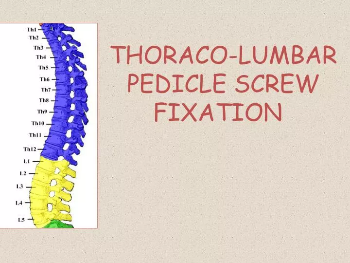
Surgical anatomy • 12 thoracic vertebrae • Typical:T2-8 • Atypical:T1,T9-12 • Transitional:T9-12 • TL junction:T11-L2 • Very vulnerable to trauma: mobile segment, absent rib cage • Upper:T1-4 • Middle:T5-T8 • Lower:T9-T12 • 5 lumbar vertebrae
Pedicle anatomy • Strong bridge between anterior and posterior columns • Strong shell of cortical and core of cancellous bone • 3 termiologies to be familiar with- • T4-T6 pedicles smallest; T12 largest • Pedicle diameters: • T4-T1: 5.6-7.9 mm • T4-T9: 4.7-6.1 mm • T10-T12: 6.3-7.8 mm Transverse /coronal pedicle angle • Transverse pedicle width • Sagittal pedicle angle Spine surgery:Benzal 2nd edition Page:1519
Indications • Traumatic fractures with instability • Stabilization after neural decompression for tumour/ infection • Deformity correction • Contraindications: • Significant osteoporosis • Medical illness precluding major surgery
Techniques of fusion of TL spine • In situ fusion • Wiring • Sublaminar wires • Inter facet wiring • Spinous-facet wiring • Hooks • Laminar hooks • Pedicle hooks • Transverse process hooks • Harrington system • Wire-rod: • Luque system • Scott wiring • Screws: • Translaminar facet screws • Vertebral screws • Pedicle screws • Plate system • Rod system
Types of pedicle screw fixationStraight-forward/free hand • Popularized by Suk and Lenke • Starting point- in the region of the transverse process-laminar facet junction, typically just lateral to the vertical line bisecting the superior facet.
Funnel technique • Described by Gaines • Utilizes a starting point within the transverse process proper, creating a 6- to 10-mm defect in the posterior cortex.
In-out-in/ extrapedicular technique • Described by Vaccaro. • Utilizes a far lateral starting point on the posterior cortex of the transverse process, perforates the ventral cortex of the transverse process, enters the lateral aspect of the pedicle, and passes into the vertebral body. • This technique generally requires an extreme medially angled trajectory to achieve purchase in the vertebral body.
Technique proper • Thoroughly review of pre-op imaging • Bone quality • Pedicle width and • Screw trajectory • Position-prone • Radiolucent table-if AP images are required
Technique (contd.) • Midline vertical incision • Subperiosteal dissection upto lateral margins of transverse processes keeping inter-transverse membrane intact • AP image • Placement of screws (awl/burr to remove cortical bone at entry site- drill-sound probe-tap-screw) • Decortication of adjacent bone (lateral aspect of facet joints and transverse process) • Facet joints can be opened and filled with cancellous bone to enhance fusion • Rods of appropriate lengths placed • Also, interconnecting cross fixation rods placed at 1-2 levels
Technique (contd.) • Entry points • Trajectory • Medio-lateral angle • Cranio-caudal angle • Length and width of screws • Distraction/compression
Entry points Lumbar spine Junction of a line bisecting transverse process and a vertical line just lateral to IAF
Screw lengths • Typically 70-80% of length of vertebral body • Upper thoracic:30-35 mm • Mid thoracic:35-40 mm • Low thoracic:40-45 mm • L1-L4:40-45 mm • L5:45-50 mm
Minimally invasive technique/ percutaneous pedicle screw placement • First described by Magerl-1977 • Newer sophosticated technique by Foley- 2002 • Fluoroscopic navigation/ CT navigation/ robotics • Advantages: • Less blood loss • Less post op pain • Less muscle dissection and post op muscle weakness • Shorter hospital stay • Schizas C et al. Computer tomography assessment of pedicle screw insertion in percutaneous posterior transpedicular stabilization. Eur Spine J 2007;16:613-7. • Ravi B et al. Clinical accuracy of computer-assisted twodimensional fluoroscopy for the percutaneous placement of lumbosacral pedicle screws. Spine (Phila Pa 1976) 2011;36:84-91. • Laine T et al. Accuracy of pedicle screw insertion with and without computer assistance: a randomised controlled clinical study in 100 consecutive patients. Eur Spine J 2000;9:235-40.
Trans-facet pedicle screw placement In lumbar spine, equivalent stability between the two Ferrara et al. Spine 2003; vol 28:1226-34 • Akbay et al-2005 • 5 cadaveric specimens; thoracic spine • Compared biomechanical stability of PSF and FSF • Entry point- junction of 2 lines • Medial border of facets • Inf border of tr.process • Trajectory: • Transverse-10 to 15 deg lat • Sagital-50-55deg inferior • FSF may be a viable alternative to PSF
Use of ball-tip probe for PS placement • Specially designed ball tip probe consisting of a ball-shaped tip with a flexible metal shaft is used to make a guide hole into the pedicle. • Incidence of misplaced screws was 14% in the ball tip group and 34% in the conventional group • Ball tip technique is useful for the accurate and safe placement of TPSs in deformed spines. • Watanabe K et al. Ball tip technique for thoracic pedicle screw placement in patients with adolescent idiopathic scoliosis. J Neurosurg Spine. 2010 Aug;13(2):246-52.
Intra-op neuro-monitoring in PS placement • SSEP, MEP, EMG (triggered/ stimulated) • EMG monitors the motor tracts through needles placed in laminae of cervical spine. • Pedicle screw stimulation via evoked EMG thresholds for <11mA are known to be associated with possible pedicle violation by the screw. • Concluded that evoked EMG to assess pedicle screw placement with stimulation thresholds >11 mA provides >97% negative predictive value for reassurance to the surgeon. • Shi YB, Binette M, Martin WH, Pearson JM, Hart RA, “Electrical stimulation for intraoperative evaluation of thoracic pedicle screw placement”, Spine (2003);28(6): pp. 595–601
Gunnarson et al- prospective study of 200 pts; EMG- 100% sensitive and 23.5% specific; SSEP- 28% sensitive and 94% specific in detecting neural injury. Combination of SSEP and EMG provides the best neuromonitoring.
Post op assessment • On X-rays, screw that appears to cross midline/ any suspicious screws- evaluate with CT • Is CT better in assessment- Definitely yes, but not the best. • Fayyazi et al-when compared to open inspection- sensitive-71%, specific-75%, accuracy-76% • Rao et al- sensitive-8^%, specific-85%, negative predictive value-63% • CT is useful in detection of malposition but in cases of neurologic/ great vessel/ lung injury-direct exploration is the best
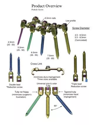
Hardware characteristics • Rigid pedicle fixation systems to be used-rigid plate/ screw-rod • Transverse interconnecting rods • Screw characteristics: • Diameters-4.5 to 7 mm • Length-30 to 55 mm with 5 mm increments • Self-tapping/non tapping screws • Mono/polyaxial screws • Screw strength is proportional to inner/minor diameter- (distance from base of one thread to base of opposite thread) • Larger the diameter, greater the resistance to screw breakage • Outside diameter- important in screw pull out resistance
Advantages • Rigid 3-column support of spinal elements, thus providing stability necessary for spinal arthrodesis • Resists motion in all planes • Better pull-out strength • Independent of facet/laminar/spinous process integrity • Avoids placement of instrumentation in spinal canals such as sublaminar wires and hooks • Allows for incorporation of fewer normal levels • Less post op bracing requirement and earlier mobilisation • Improved fusion rates as compared to other instrumentation and non instrumented fusions
Disadvantages • Steep learning curve • Extensive tissue dissection needed to expose starting points • Lengthy surgeries and blood loss • Significant pain • Significant osteoporosis is a relative contraindication • Rigid fixation can accelerate adjacent segment degeneration • Expensive procedures
How to increase pullout resistance of pedicle screws • Length of screw-2/3rds of body • Larger diameter screw • Larger pitch of screw • Use of rod/plate systems • Screw-rod junction subject to greatest strain- so tapering screws are used
Use of interconnecting/ cross fixation rods • At junction of upper/mid 1/3rd; lower/ mid 1/3rd . • Not more than two in number • Screw trajectory- Straight on trajectory rather than following pedicle • Lehman et al (Spine 2003)
Complications • Malpositioning/ pedicle screw violations-most common- 0-44% • 3 grades (Youkilis et al) • Grade1-screws replace cortex without extending beyond pedicle margin • Grade2-< 2 mm cortical breach • Grade3- 2-4 mm cortical breach • Intentional lateral entry- in cases of smaller thoracic pedicles • True violations • Grade 4-> 4 mm cortical breach
Gertzbein and Robins- 4mm safe zone of allowable medial encroachment. • Belmont- defined the acceptable limits as 2 mm of medial wall penetration and 6 mm of lateral wall penetration. • Clinically, encroachment of the epidural space up to 2mm is conservatively considered to be safe in most cases • Gertzbein SD, Robbins SE. Spine 1990;15:11-5
Remember: Cortical violations does not mean neurological deficit • Violations > 6 mm- present with neurological deficits • How to avoid: Appropriate entry point/ screw diameter/ under-vision technique • Pedicles which are laterally directed/ scaphoid/ <4mm coronal diameter- Intentional lateral entry • Endoscope probe- to assess the intactness of pedicle screw • Frank et al-Neurol Res 1997 • A-mode ultrasound for pedicle screw advancement • Raphael et al: Spine journal May 2010
Hardware problems • Screw loosening- • Rare; delayed complication • Seen as lucency around screw on x-rays • Indicates fusion delay/pseudoarthrosis • May be due to inadequate screw purchase/reduced bone density (osteoporosis) • Screw pullout/toggle • Screw fractures (mostly at screw-rod junction) • Inappropriate entry site/ trajectory angle /very large screw
Neurological- • Spinal cord/ nerve root injury • Dural tears-CSF leak/fistula • Direct repair/ seal the pedicle defect with gelfoam soaked in glue/thrombin • Vascular- • aorta injury (with left sided screws) • Visceral- • Pleural/lung injury • Local- • Pedicle fractures
Precautions • Thin patients- use low profile constructs • Osteoporosis- • Involve multiple levels of fixation, if performed • Use cannulated and augmented screws • Pedicle screws in scoliosis: • Challenging; pedicle smaller and scletoric on the concave side; spinal cord is also proximal to pedicle on the concave side
Literature • Dickman et al (1992)- • 104 cases: 517 pedicle screws • 4 (0.05%) – neurological problems • 18 (1.8%)- implant failure • 96% fusion rate at 20 months FU
Liljenqvist (1997) et al. • 32 patients with idiopathic scoliosis who underwent thoracic pedicle screw fixation; 160 screws placed. • Screws placed from T4 to T12 by use of anatomic landmarks and fluoroscopy. • Cortical penetration rate of 25%, evaluated by plain x-rays and thin-cut CT scans. • Upper thoracic spine (T4–T7, 35.3%) v/s lower thoracic spine (T8–T12, 23.3%). • Medial penetration occurred in 8.3% of the thoracic screws placed. • No neurological deficits; 1- very proximal to aorta • Liljenqvist UR, Halm HF, Link TM: Pedicle screw instrumentationof the thoracic spine in idiopathic scoliosis. Spine 22:2239– 2245, 1997.
Youkilis et al (2001) • 65 pts; 266 screws; • Image-guided- Stealth station guidance system • Cortical perforations (8.5%) • Structurally significant violations (2.2%) • No fresh deficits/ visceral/ vascular injuries • Youkilis et al .Stereotactic navigation for placement of pedicle screws in the thoracic spine Neurosurgery. 2001 Apr;48(4):771-8
Parker et al (2011) • 964 pts; 6816 free hand PS placement • 9% cortical violations • Cortical breach: Th> Lumbar; Lat>Med • T4 and T6 highest breach • 0.8%- revision surgery • Parker SL et al. Neurosurgery. 2011; 68(1):170-8
Is navigation guidance better? • Abibtol et al-1996 • Cadaveric study • Compared conventional (fluoroscopy+ anatomical landmarks) v/s image guided screw placement • 48 screws placed T1-T12 • Cortical violations- 50% in group1 and 4% in group 2
Using anatomical landmarks- cortical violations: 15-54% • Navigation assisted:3.7-38% • Kim et al Spine 2001; Belmont et al Spine 2001
Tian et al (2011) 43 studies Traditional v/s navigation Pedicle violations significantly less with navigation systems Eur Spine J. 2011 Jun;20(6):846-59.
Gelalis et al (2012): 26 prospective studies; 1100 pts; • Good placement • Free hand- 68-94% • Fluoroscopic-28-85% • CT navigation-89-100% • Navigation does indeed exhibit higher accuracy and increased safety in pedicle screw placement than free-hand technique and use of fluoroscopy. • Eur Spine J.2012 Feb;21(2):247-55.
Radiation exposure • Both patient and surgeon • Rampersaud et al- radiation exposure to surgeon’s hands, neck and torso • Recommended annual hand exposure- 50000 mrem. • Average hand exposure- 58 mrem/min. • Average exposure was 9.3 s/screw • A surgeon would exceed occupational exposure limit for the eyes and extremities by placing 4854 and 6396 screws percutaneously, respectively • So, use whenever necessary; keep hands out the beam while radiation exposure • Rampersaud YR et al. Spine (Phila Pa 1976). 2000;25:2637–2645. • Mroz TE et al. J Spinal Disord Tech 2011;24(4):264-7
General comments • Lower thoracic and lumbar • Gold standard • Larger pedicle size • Safety zone from T10-L4 • Anterior violations less dangerous • Lateral violations often asymptomatic • Several clinical and anatomic studies • Upper and middle thoracic • Challenging • Adherence of thoracic viscerae to ALL • Smaller pedicle size- pedicle # and violations • Smaller canal diameter • Lateral violations dangerous to pleura, great vessels, esophagus Always master lumbar pedicle screws, then only perform thoracic pedicle screws Begin with trauma/ tumour- later, do deformity
Conclusions TL spine is affected by a number of conditions that can cause instability Pedicle screws are the most rigid fixation technique and form the mainstay of treatment of spinal instability. Thorough knowledge of surgical anatomy, pre-op imaging assessment, optimal screw selection can help prevent complications Master lumbar screws before doing thoracic. Free hand technique-equally good Keep radiation exposure to minimum