Download
1 / 17
170 likes | 261 Vues
LPC-analysis-VOSIM-resynthesis. Combined class December 18 th 2012 Johan & Peter Institute of Sonology Royal Conservatory, The Hague. A(t). t. A(t). F. F. t. s(t). t. AM model. constant. A(t). t. A. F(t). F. t. s(t). t. FM model. constant. A(t). t. A(t). F(t). F(t).

E N D
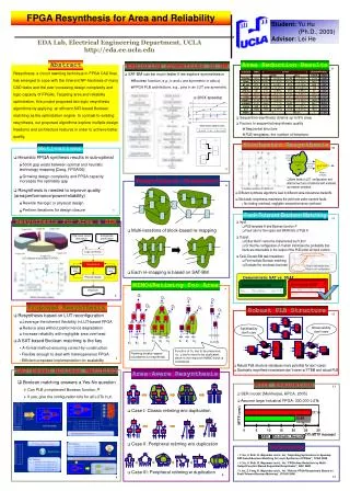
LPC-analysis-VOSIM-resynthesis Combined class December 18 th 2012 Johan & Peter Institute of Sonology Royal Conservatory, The Hague
A(t) t A(t) F F t s(t) t AM model constant
A(t) t A F(t) F t s(t) t FM model constant
A(t) t A(t) F(t) F(t) t s(t) t FM & AM combined:Instantaneous Frequency (IF)-model
Model: one “phasor” or sine wave with amplitude and frequency varying over time. • One sine wave only, no other frequency components!? • But with FM we can create complex waveforms! • Rapid amplitude changes will deform the sine wave too and also create a more complex waveform…. So: • The frequency width or content depends on the speed of variation that we allow for the control. • Another key concept is: To what degree is a description “band limited”
Fourier model Amplitude only[bands with constant frequency] A A Frequency Sweep A time
Example: exponential sweep through octave bands 11 kHz .. > 22 kHz 5,5 kHz .. 11 kHz 2750 Hz .. 5,5 kHz 1375 Hz .. 2750 Hz . 688 Hz .. 1375 Hz 344 Hz .. 688 Hz 172 Hz .. 344 Hz 86 Hz .. 172 Hz 43 Hz .. 86 Hz < 43 Hz
Model: one “phasor” or sine wave with amplitude and frequency varying over time. • The frequency width or content depends on the speed of variation that we allow for the control. • The frequency width or frequency content controls the speed of variation that of the A(t) and F(t) signals. • The key concept is: To what degree is a description “band limited”? • Other useful insight: Phase change per time step is frequency.
Phase Vocoder! [still bands with constant frequency]Fourier model, +phase change (=freq.) info A F A Frequency F Sweep A F time
Options: • FFT (narrow band): -Many bands closely spaced, -Reduced frequency and amplitude variation.-Slow update [frame-by-frame] of A(t) and F(t) info.-Take-over points produce ripples. • Wide bands (today):-A(t) and F(t) vary over larger ranges.-faster variations and more continuous. • One band only (Can you implement this? Yes you can!):-Instant A(t) and F(t) update per sample.
LPC is an (inverse) filter design method. • It is mathematical procedure based on matrix calculus / linear algebra. • It is not one method but a group of methods. • It designs an “inverse” filter that could optimally remove the spectrum energy that exist in a certain signal. • It does this by searching the best band stop filters to remove the energy in a resonance. • If you know the best setting to remove energy, than you know the frequencies and bandwidths of the resonance frequencies too.
LPC is an (inverse) filter design method. • Input is typically a signal that is spectrally shaped by band filtering. • Next, the filter order (div 2) controls the number of anti-resonances that are modeled. • The result of the design procedure is a so-called error signal or residue which indicates how successful the process was. • Successive removal of resonances will result in lower energy error signal that spectrally is maximally flat or white. • This error signal or residue may still be periodic and thus have a harmonic structure.