Download
1 / 19
200 likes | 356 Vues
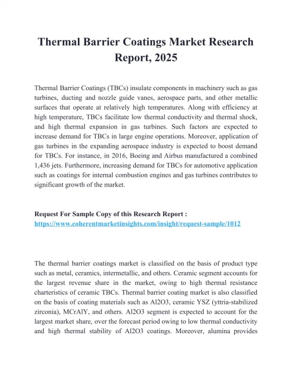
The Effect of Bond Coat Oxidation on the Endurance of a Thermal Barrier Coating System. R D Jackson, Dr M P Taylor, Prof H E Evans The University of Birmingham, Edgbaston, Birmingham, B15 2TT. The authors acknowledge the funding, provision of specimens and guidance from Siemens, UK. Coating.

E N D
The Effect of Bond Coat Oxidation on the Endurance of a Thermal Barrier Coating System R D Jackson, Dr M P Taylor, Prof H E Evans The University of Birmingham, Edgbaston, Birmingham, B15 2TT The authors acknowledge the funding, provision of specimens and guidance from Siemens, UK.
Coating 12mm 3.5mm Substrate Materials • Substrate is the Ni-based single crystal superalloy CMSX-4 • Bond coat is a CoNiCrAlY applied by HVOF • Topcoat is a 7wt% yttria partially stabilised zirconia applied by EBPVD
YSZ top coat TGO CoNiCrAlY bond coat Oxidation between splats Interdiffusion zone Superalloy substrate Section Through the As-Received TBC
SEM Image of a Section Through a Specimen Oxidised for 8hr at 1150°C β-phase in mass % γ-phase in mass %
Oxidation Tests • Specimens were isothermally tested in laboratory air at 50°C increments from 950°C to 1150°C for up to 3000hr. • After testing the specimens were sectioned and prepared for examination using a FEG-SEM. • 10 micrographs were taken of representative regions of the bond coat / topcoat interface across the width of the coating. • From each of these micrographs 10 thickness measurements were made of the TGO i.e. a total of 100 readings for each specimen.
Oxide Growth Distributions • All specimens tested were found to follow a normal Gaussian distribution at the all tested times and temperatures. • However the standard deviation of the measured results increased with increasing time at temperature • This could be due to localised increased oxidation rate which persists over time.
Oxide Growth Kinetics • The value of the time exponent, n, in all cases was greater than 2. • Values ranged from 2.5 at 950°C to 3 at 1150°C • This may be due to coarsening of the oxide grains, reducing “short circuit” diffusion pathways, or variations in stress gradients across the oxide layer. • In order to compare to other literature values a pseudo-parabolic relationship was calculated using the method described by Hindam and Whittle. • This showed a reasonably good fit to the predicted line for alumina formers
, m2s-1 Oxide Growth Kinetics
XRD Analysis of the TGO formed at 1150°C over 50h The principal peaks of -alumina and zirconia
Coating Failure • Final failure of the specimens occurred in all cases at the TGO/bond coat interface during cooling. • This effect is likely caused by the mis-match in thermal expansion co-efficients between the topcoat/TGO and the substrate and bond coat. • However, sub-critical cracking and delamination was seen in some specimens after sectioning.
Sub-Critical Cracking and Delamination A B linked cracks (A) Oxidised for 2 hr at 1050°C. (B) Oxidised for 25h at 1150°C
FEA Oxide Growth on Non-Planar Surfaces Contour of maximum out-of-plane principal stress near the TGO layer at 1100°C after 100 hours oxidation at 1100°C in a TBC system when BC and TGO creep and top coat sintering are considered. (a) b / a = 0.52 and (b) b / a = 0.
Conclusions • Coatings produced where typically dual phase, β plus γ, with a dense alumina TGO already formed at the outer surface during manufacture. • TGO growth kinetics show sub-parabolic behaviour which is most likely due to coarsening of oxide grains. • Growth kinetics and lifetimes fit well with typical theoretical and literature data. • 2 failure methods exist: • Sub-critical linked cracks at the base of the topcoat due to out of plane stresses in and around oxide caused by growth on a non-planar surface. • Final failure always occurred at the TGO/bond-coat interface, however.