Download
1 / 47
650 likes | 1.18k Vues
Basic TFT LCD ELOP. Judy Chu Display Dpt. 2012/11/06. What is light. "Visible light" redirects here. For light that cannot be seen with human eye, see Electromagnetic radiation. For other uses, see Light (disambiguation) and Visible light (disambiguation). E: 電場方向. Visible light.

E N D
Basic TFT LCD ELOP Judy Chu Display Dpt. 2012/11/06
What is light • "Visible light" redirects here. For light that cannot be seen with human eye, see Electromagnetic radiation. For other uses, see Light (disambiguation) and Visible light (disambiguation). E: 電場方向
Polarization Vertical linear polarized Circular polarized Horizontal linear polarized
Polarizer • A polarizer is an optical filter that passes light of a specific polarization and blocks waves of other polarizations. It can convert a beam of light of undefined or mixed polarization into a beam with well-defined polarization Polarizer
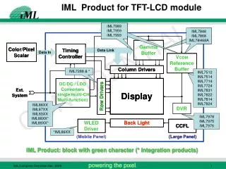
LCD Module Structure Polarizer CF (Color Filter) LC Cell (Panel) Module Array Polarizer Back Light + PCB
Upper Lower Glass substrate LC director Glass substrate ψ= 90o ψ= 0o ψ= 180o ψ= 270o Grey Scale Inversion TN-GSI (Gray Scale Inversion)
Display Characteristic and Measurement • Luminance • Contrast Ratio • Viewing Angle • Chromaticity • Response Time • Gamma curve • Flicker
Luminance 定義為當顯示全白畫面下,垂直顯示器方向所得到光的亮度。單位為cd/cm2,有時也會使用nit的單位。
L(White) CR= L(Black) Contrast ratio • 一個顯示畫面的內容,是由畫素與畫素之間的差別來表現。這個差別可以用最亮的亮度與最暗的亮度之比率,作為量化的指標,此比例即為對比
Viewing angle-Iso-contour White Black CR
Response time What doesResponse time means : Where tr is the total on time, td is the total off time, d is the cell gap, Vapp is LC applied voltage, K is the elastic constants of the liquid crystal mixture and h is the viscosity of the liquid crystal mixture
Response time Faster response Slower response
Chromaticity -- Structure of Human Eye • The retina is a mosaic of two types of photoreceptors, rods and cones. • Rods are sensitive to blue-green light with peak sensitivity at a wavelength of 498 nm, and are used for vision under dark or dim condition
Spectrum x = x
X Y Z x = y = z = X+Y+Z X+Y+Z X+Y+Z Chromaticity—CIE1931 color coordinate • Tri-stimulus values X =k∫ P(λ) ρ(λ) x(λ)d λ Y =k∫ P(λ) ρ(λ) y(λ)dλ Z =k∫ P(λ) ρ(λ) z(λ)d λ *x(λ) , y(λ) , z(λ) :color matching function • Chromaticity coordinates(x,y) CIE 1931(x,y) chromaticity coordinates
EBU: European Broadcasting Union Color saturation index RGB NTSC ratio= 100 % NTSC color gamut 1931 CIE Chart showing the color gamut of an RGB display Chromaticity--NTSC • NTSC ratio (National Television System Committee
Chromaticity--NTSC Lower NTSC% Higher NTSC%
Gamma Picture by different gamma setting Gamma =3 Gamma =2 Gamma =1
+ - - - - VExt VInt + + + + - VLC = VExt - VInt Image retention( sticking)
Flicker—Polarity inversion • Liquid crystal must be driven with an alternating current to prevent any deterioration of image quality resulting from dc stress. This is usually implemented with a frame-reversal drive method, in which the voltage applied to each pixel varies from frame to frame. If the LC voltage changes unevenly between frames, the result would be a 30-Hz flicker.(One frame period is normally 1/60 of a second.)
T% Vlc N+2 N+3 N+1 frame N V+ V- 1/30 S Time Flicker—measurement Vlc+= V+-VcomVlc-= Vcom-V- The optimized Vom Vlc+=Vlc- Vcom Vlc+ ≠Vlc = flicker ~ L186 (sharp area)luminance is depends on Vlc Measurement : light voltage Luminance level Time
Flicker (dB) Optimum Common Electrode Voltage Common Electrode Voltage(Vcom)V Flicker—measurement Flicker= AC component/ DC component (%) Digital Fourier transfer
Flicker-improvement • Adjust Vcom to make LC applied voltage symmetrically • Reduce current leakage from TFT and LC • Increase frame rate • Changing driving scheme.