Download
1 / 24
240 likes | 350 Vues
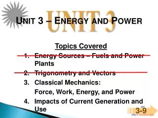
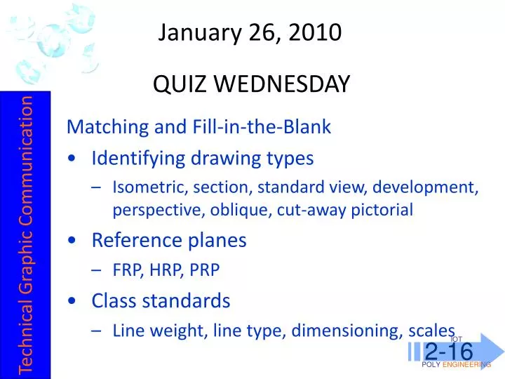
January 26, 2010. IOT POLY ENGINEERING. 2-16. QUIZ WEDNESDAY. Matching and Fill-in-the-Blank Identifying drawing types Isometric, section, standard view, development, perspective, oblique, cut-away pictorial Reference planes FRP, HRP, PRP Class standards

E N D
January 26, 2010 IOTPOLYENGINEERING 2-16 QUIZ WEDNESDAY • Matching and Fill-in-the-Blank • Identifying drawing types • Isometric, section, standard view, development, perspective, oblique, cut-away pictorial • Reference planes • FRP, HRP, PRP • Class standards • Line weight, line type, dimensioning, scales Technical Graphic Communication
IOTPOLYENGINEERING 2-10 review AUXILIARY VIEWS 2 • So far, our standard 6 views are all visible using the three regular planes of projection • Frontal Reference Plane • Horizontal Reference Plane • Profile Reference Plane • Those views are drawn TRUE SIZE • However, inclines (slants) are not shown as true size in standard views. TYPE 2: MULTI-VIEW
HRP IOTPOLYENGINEERING 2-10 PRP FRP reviewAUXILIARY VIEWS 2 • Inclines (slants) are not shown as true size in standard views. • Each square below represents 1”. What are the widths of the front view and right side views? • 9” and 4”, respectively TYPE 2: MULTI-VIEW • Neither the front, top, or side view shows the true size and shape of the object’s inclined surface.
IOTPOLYENGINEERING 2-10 Review AUXILIARY VIEWS 2 The ARP shows true form (shape and size) for inclines Which Reference Plane? HRP Auxiliary Reference Plane ARP TYPE 2: MULTI-VIEW PRP FRP
IOTPOLYENGINEERING 2-10 review ISOMETRIC 3 • From Greek: Equal Measure • Isos: Equal • Metron: Measure • The scale along each axis of the projection is the same • True form parallel lines are shown as parallel (note colors below) • All isometrics: simple construction TYPE 3: PICTORIAL Isometric Cube: 1) all lines equal length; 2) all faces equal area; 3) perimeter is a hexagon
IOTPOLYENGINEERING 2-10 Review PERSPECTIVE 3 • Latin: perspicere – to see through • An approximate representation of an image as it is perceived by the eye. • The most characteristic feature of perspectives is that objects are drawn: Smaller as their distance from the observer increases TYPE 3: PICTORIAL
IOTPOLYENGINEERING 2-10 Review OBLIQUE 3 • A way of showing depth, like isometric • Part orthographic / part isometric: • One face is true form • Parallel lines behind; either: • Full scale • Half scale • Three-quarter scale TYPE 3: PICTORIAL
IOTPOLYENGINEERING 2-10 Review CUT-AWAY PICTORIAL 3 • Show the interior details of a product • Often employed in instruction manuals • Assists in understanding operation of product TYPE 3: PICTORIAL
IOTPOLYENGINEERING 2-11 Review • Turn in your 3-view assignment (include NAME) • Match the type of Technical Graphics below with its type: Isometric Section Standard View Development Perspective Oblique Cut-away Pictorial B C A E B C F G D A D E F • Communication Technology G
IOTPOLYENGINEERING 2-11 Review LINE WEIGHTS Four Weights in this class: Light: not noticeable from 2’ (nearly invisible) Medium: just noticeable from 2’ Heavy: obvious from 2’ (final weight for most objects) Very Heavy: only used for borders Technical Graphic Communication
IOTPOLYENGINEERING 2-11 review LINE TYPES • Construction/Layout Lines • LIGHT WEIGHT • ALL lines begin as these • DO NOT ERASE (unless there is a measuring error) • Guidelines • LIGHT WEIGHT • Used for LETTERING CLASS STANDARDS
IOTPOLYENGINEERING 2-11 Review LINE TYPES • Object Lines: • HEAVY WEIGHT • The final line type for most objects • Hidden Lines: • HEAVY WEIGHT • Everything must be represented in each view, whether or not it can be seen • Interior and exterior features are projected from view to view in the same way • Parts not seen on the exterior of a view are drawn with hidden lines – short DASHES CLASS STANDARDS
IOTPOLYENGINEERING 2-11 Review SCALES • Objects to be drawn may be small • Nanotechnology machine parts, for example • Objects to be drawn may be big • Buildings, bridges, airliners, oil rigs, trucks, cars • Full Scale drawings will not always fit on a sheet of paper • Scale down or scale up ½” = 1’-0” ¼” = 1’-0” 1” = 14’-0” • Scale must be indicated in your title block • Architect’s Scale, Engineer’s Scale, Metric Scale make scaling drawings simpler. CLASS STANDARDS
IOTPOLYENGINEERING 2-16 ORTHOGRAPHIC PROJECTIONS • Due by end of class Today • Use spacing of .5” between views for second Orthographic Projection Technical Graphic Communication
1. Draw ½” border 2. Draw a 5/16” title block 3. Add 2 LIGHT lettering guidelines, 1/16” from border lines 4. Add scale separator – Heavy Weight ½” 5/16” 1 ¾” • LETTER the title block information: • BPI-IOT ORTHO PROJ 1 17 OCT 08 LAST, F FULL SCALE
5. Measure the overall width and height of drawing space W H
HORIZONTAL STARTING POINT 1. Add width of front view to width of right view. 2. Add the space we will put between: 1.5” 4” 1.5” 1.5” 4” + 1.5” + 1.5” = 7”
3. The remaining space is equal to W – 7” = ~3”. 4. Divide the remaining space by 2 to get horizontal pt. Horizontal Starting Point is 1.5”
VERTICAL STARTING POINT 1. Add height of front view to height of top view. 2. Add the space we will put between: 1.5” 1.5” 1.5” 2.5” 2.5” + 1.5” + 1.5” = 5.5”
3. The remaining space is equal to H – 5.5” = ~1.75”. 4. Divide the remaining space by 2 to get vertical pt. Vertical Starting Point is 7/8”
DRAWING ORTHOGRAPHIC PROJECTIONS • Draw border and title block • Locate starting point to center drawing (use construction) • Construct front view and PROJECT lines across paper • Construct top view and PROJECT lines across paper
DRAWING ORTHOGRAPHIC PROJECTIONS • Locate the top-most, right-most intersection of front view construction lines. • Use a 45-deg triangle and project a miter line. • Project lines down for right view. DO NOT ERASE CONSTRUCTION LINES THEY FADE IN COMPARISON TO OBJECT LINES DARKEN what needs to be DARKENED