Download
1 / 19
190 likes | 308 Vues
Beam Measurements After the Sources a t the Ion S ource Test Stand Including H 2 , N 2 and Kr Gas Injection. Lots of input from Cristhian, Jan, Chiara, Nicolas, Roberto, Albin, Federico, Francesca, Jean-Baptiste, Jacques, Oystein …. R Scrivens, Linac 4 10/04/2014. LEBT. Source.

E N D
Beam Measurements After the Sources at the Ion Source Test Stand Including H2, N2 and Kr Gas Injection Lots of input from Cristhian, Jan, Chiara, Nicolas, Roberto, Albin, Federico, Francesca, Jean-Baptiste, Jacques, Oystein … R Scrivens, Linac 4 10/04/2014
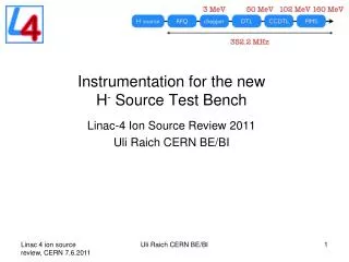
LEBT Source Plasma G Extraction
Set up • At the Ion source Test Stand (drawing is not fully accurate) • Solenoid, 1 Steerer • Prechopper – grounded • Gas Injection (not on for all measurements) • Faraday cup • SEMGrid • Emittance meter
4 Plasma Generators Compared Intensity
Emittance H – sol=90A IS02-25kW DESY-20kW IS02-40kW IS02-Cs-90kW
Data Summary – For Measurements on Prev Slide Currents are from the Faraday Cup scan. Not the max achieved.
If we switch to an IS01 in the tunnel • What would be the conditions with an IS01 in the tunnel? • This is the proposal being put forward by us for 12MeV commissioning. • Today’s closest measurement to this source configuration is the “IS02-40kW uncesiated” from 10/12/2013. • Jean-Baptiste has transported this beam through the RFQ and sees a similar 68% transmission (to DESY). • But the intensity from the source is >50% greater than DESY. IS02-40kW
Do the Simulations Match? • Simulations can be made from Source Plasma to Emittance Meter. • Uses IBSIMU (a C++ library for plasma->beam extraction) • OysteinMidttun has extensively studied the currents in the extraction region to refine the simulations. • Transfer this beam to the LEBT and emittance meter (using space-charge compensation of trapped ions) – Cristhian Valerio. Simulation real data Solenoid 100 amps Horizontal Outliers are coming from the “edge” of the beam. In turn they came from the edge of the source aperture.
High current, unbunched beams are compensated by ions created by the beam striking the residual gas. • Electric field from the beam can be reduced by 80%. This make a large difference to the beam transport at low energy. • At Linac4 we have foreseen to be able to adjust the pressure in the LEBT to allow control over the generation rate of these secondary ions. • Its been operational at Linac4 since the beginning. • A rather complicated control loop (PH-DH -> BE-ABP -> TE-VAC) stabilises the pressure in the LEBT. Dynamic H2 pressure
Cristhian Valerio made tests in the Source Test Stand with 3 different gases: • H2 : Present anyway, sure will not affect the source. • N2 : Safe, easy to pump. • Kr : High cross section for ionization, heavy, hard to pump with getter based pumping. • For each gas we measured the beam emittance for a range of injection pressures. • The source was maintained at 30mA with daily correction of the RF power (it was in cesiated mode). • The full series of measurements took about 2 weeks. • At the test stand we do not have a pre-chopper, so the rise of the source pulse is also visible.
From the emittance meter data, we reconstruct the beam SIZE as a function of time in the pulse. • From this we derive a stabilisation for that measurement. • Higher pressure -> shorter stabilisation time. • We need to run Linac4 with a stabilisation time of approx 25us.
The Final Results…. e is the statistical phase space emittance for all data “SEJ -> SEJ+350us”
Within the error bars, there is nothing to strongly conclude one gas is better than another for beam transport reasons. • However the cross sections for ion production of the gases is different, such that for the same stabilisation time requirement, we could operate at H2 1x10⁻⁵ mbar == N2 5x10⁻⁶mbar == Kr 2.5x10⁻⁶mbar (examples) • Heavier N2 and Kr would reduce flow into the RFQ. • But for Kr NEG pumps and ion pumps are inefficient. • Propose to test N2 at Linac4, to see effect on RFQ. • Carlo agrees for RFQ for a test. • Vacuum agree pressure in RFQ should be lower, and pump lifetime higher. • Could we do a test within DTL commissioning period. • Start up with H2 • 1 day to switch gas, restart source / LEBT and recover beam through RFQ. • 1 day to switch back to H2 if bad results. • H2 will still be present from the source. RFQ vacuum gauges would reduce by a factor 2 only (whereas the gas density will be a factor 4 lower). • For the long term effects on a Cs source, we would switch to N2 at the source test stand in the future.
Summary and Conclusions • Multiple plasma generators measured. • An IS01 could be ready soon, and should lead to more beam through the RFQ. • N2 could be a better alternative as a LEBT gas for the RFQ.