Download
1 / 77
770 likes | 947 Vues
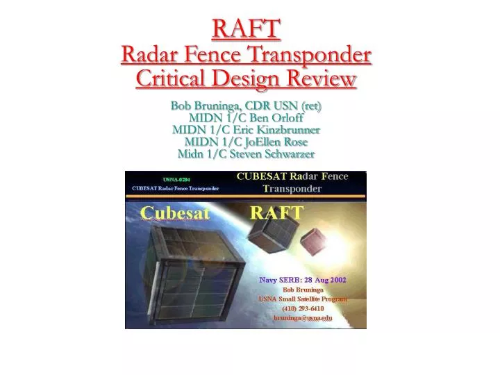
RAFT Radar Fence Transponder Critical Design Review. Bob Bruninga, CDR USN (ret) MIDN 1/C Ben Orloff MIDN 1/C Eric Kinzbrunner MIDN 1/C JoEllen Rose Midn 1/C Steven Schwarzer. Key Milestones: Schedule. Assumption: Launch NET February 2006 RAFT Kickoff Apr 04

E N D
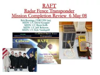
RAFTRadar Fence TransponderCritical Design Review Bob Bruninga, CDR USN (ret) MIDN 1/C Ben Orloff MIDN 1/C Eric Kinzbrunner MIDN 1/C JoEllen Rose Midn 1/C Steven Schwarzer
Key Milestones: Schedule • Assumption: Launch NET February 2006 • RAFT Kickoff Apr 04 • RAFT USNA SRR Sep 04 • RAFT PDR19 Nov 04 • RAFT Phase 0/1 Safety 16 Dec 04 • RAFT Phase 2 Safety 10 Feb 05 • RAFT CDR 23 Feb 05 • RAFT Flight Unit Testing May 05 • RAFT Phase 3 Safety Aug 05 • RAFT Delivery/Install Oct 05 • RAFT Flight (STS-116) 09 Feb 06
So Many CUBEsats 30 to 50 in Construction How to Track them??? AIAA/USUSmall Sat Conference 30% of papers were for PICO, NANO and CUBEsats All smaller than 10 cm
Mission Statement • To provide the Navy Space Surveillance (NSSS) radar fence with a means to determine the bounds of a constellation of PicoSats otherwise undetectable by the radar fence • To enable NSSS to independently calibrate their transmit and receive beams using signals from RAFT. • This must be accomplished with two PicoSats, one that will actively transmit and receive, and one with a passively augmented radar cross-section. • Additionally, RAFT will provide experimental communications transponders for the Navy Military Affiliate Radio System, the United States Naval Academy’s Yard Patrol crafts, and the Amateur Satellite Service.
Military Affiliate Radio System • The Mission of the MARS system is to: • Provide auxiliary communications for military, federal and local disaster management officials • Assist in effecting communications under emergency conditions. • Handle morale and quasi-official communications traffic for members of the Armed Forces and authorized U.S. Government civilian personnel • Provide routine operations in support of MARSGRAMS and … contacts between service personnel and their families back home home.
Yard Patrol Craft Application Unique UHFAM Uplink and HF SSB downlink
RAFT1 and MARScom 5” Cubes 3 Antennas Each Identical Mechanical
RAFT Lifetime Estimate 3.8 Mo 6.5 Months
MARScom Lifetime Estimate 3 Mo 4.9Months
RAFTDeployment Velocity of pair: 1.5 m/s Velocity of RAFT: 1.19 m/s Velocity of MARScom: 1.91 m/s
Solar Panel Design on 5 Sides COTS Silicon Cells on PCB panel Covered with Clear Teflon Coating 1.5 Watt panel Mechanically rugged for rain/hail/birds PCsat Flight Heritage
Multi-Function Top Panel VHF Antenna holes HF whip hole Pockets for other satellite antennas and Sep Switch
RAFT1 Internal DiagramTop View Ant pocket & Sep SW
RAFT Internal Corner Detail Whip antenna and sep springs
Side Panel Detail Loaded Side .25” thick
SSPL4410 LAUNCHER: Operation 1. NEA DEVICE ACTUATES 2. LATCH ROD SLIDES FORWARD 3. DOOR SWINGS OPEN AND LATCHES 4. PICOSATs EJECT 3 4 Door in open, latched, landing position 2 No separation until after both picosats clear launcher NOTE: Top Cover and LatchtrainCover not shown in this view 1
SSPL4410 LAUNCHER: Preload and Launch Loads • For SSPL4410 with MEPSI: • PICOSAT mass m = 1.6 kg = 3.5 lbs • Preload > { 24 g x 3.5 lbs = 84 lbs } • F = 125 lb max preload + 24 g x 3.5 lb 210 lbs • 24 g calculated in SVP • For SSPL5510 with RAFT: • PICOSAT mass m = 7 kg = 15.4 lbs • Preload > { 24 g x 15.4 lbs = 370 lbs } • F = 500 lb max preload + 24 g x 15.4 lb 870 lbs credit:
Depressurization Rate .040 hole Gives 2:1 margin for depressurization
Separation Velocities Click here for entire documentation
Engineering Drawings • Top Panel • Bottom Panel • TX Panel (Page 1 / Page2) • RX Panel (Page 1 / Page 2) • HF Spool/Casing
RAFT1 Panels and Connectors Each panel one pigtail All plug into Interface Board on the PSK panel New @ CDR