Download
1 / 21

E N D
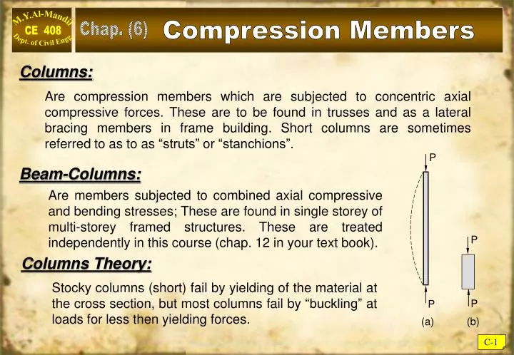
P P P P Compression Members Chap. (6) Columns: Are compression members which are subjected to concentric axial compressive forces. These are to be found in trusses and as a lateral bracing members in frame building. Short columns are sometimes referred to as to as “struts” or “stanchions”. Beam-Columns: Are members subjected to combined axial compressive and bending stresses; These are found in single storey of multi-storey framed structures. These are treated independently in this course (chap. 12 in your text book). Columns Theory: Stocky columns (short) fail by yielding of the material at the cross section, but most columns fail by “buckling” at loads for less then yielding forces. (a) (b) C-1
y y x Pcr Pcr x L Critical Buckling Load of Columns For “slender” columns, Euler (1759) predicted the critical buckling load (Pcr) – also known as Euler Buckling Load as: where: E = Young Modulus of Elasticity. I = Minor moment of Inertia. L = Unbraced length of column. Derivation of Euler Buckling Load: where: Solution of this differential equation: y = A cos (cx) + B sin (cx) , A and B are constants. C-2
The critical buckling load is a function of the section properties (A, L, r) and the modulus of elasticity for material, and is not a function of the strength or grade of the material. Note: Euler Buckling Formula From boundary conditions: y = 0 @ x = 0, and y = 0 @ x = L, we get (A = 0) and (B sin cL = 0) if B ≠ 0, then cL = n where n = 0, 1, 2, 3 ……… cL = ---- Euler Buckling Critical Load where: r = minor radius of gyration C-3
Euler Critical Buckling Load Example C-1 Find the critical buckling load for W 12 x 50, supported in a pinned-pinned condition, and has an over-all length of 20 feet? Solution: rmin = ry = 1.96 inch (properties of section). Pcr = Fcr A = 19.1 x 14.7 = 280.8 kips Note: The steel grade is not a factor affecting buckling. C-4
Stress Strain Relations in Compression For short (stocky) columns; Equation (C-2) gives high values for (Fcr), sometimes greater then proportional limit, Engessor (1889) proposed to use (Et) instead of (E) in Euler formula: where: Et = Tangent Modulus of Elasticity Et < E When (Fcr) exceeds (FPR), this is called “Inelastic Buckling”, constantly variable (Et) need to be used to predict (Fcr) in the inelastic zone. Shanley (1947), resolved this inconsistency. C-5
Column Strength Curve Depending on (L/r) value the column buckling strength was presented as shown by Shanley. Residual Stresses:- Due to uneven cooling of hot-rolled sections, residual stresses develop as seen here. The presence of “residual stresses” in almost all hot-rolled sections further complicates the issue of elastic buckling and leads towards inelastic buckling. C-6
Effective Slenderness Ratio The Euler buckling formula (C-1) is based on: 1 – Perfectly straight column. (no crookedness). 2 – Load is concentric (no eccentricity). 3 – Column is pinned on both ends. where: K = Effective length factor. (Kl) = Effective length. (Kl/r) = Effective slenderness ratio. The Previous conditions are very difficult to achieve in a realistic building condition, especially the free rotation of pinned ends. Thus an “effective slenderness factor” is introduced to account for various end conditions: Thus: see commentary (C – C2.2) (page 16.1-240) C-7
AISC Column Design Requirements AISC (Chapter E) of LRFD code stipulates: Pu (factored load) c Pn where: Pu = Sum of factored loads on column. c = Resistance factor for compression = 0.90 Pn = Nominal compressive strength = Fcr Ag Fcr = Critical buckling Stress. (E3 of LFRD) a) for b) for where: C-8
AISC Column Design Criteria The above two equations of the LRFD code can be illustrated as below: where: * The code further stipulates that an upper value for for column should not exceed (200). * For higher slenderness ratio, Equation (E-3.3) controls and (Fy) has no effect on (Fcr). C-9
Capacity of Compression Members Example C-2 Determine the design compressive strength (cPn) of W 14x74 with an untraced length of (20 ft), both ends are pinned, (A-36) steel is used? Solution: Kl =1 x 20 x 12 = 240 in Rmin = ry = 2.48 c Pn = 0.9 x Fcr x Ag = 0.9 x (21.99) x 21.8 = 433.44 kips (Answer) Also from (table 4-22) LFRD Page 4-320 c Fcr = 19.75 ksi (by interpolation) c Pn = c Fcr Ag = 430.55 kips (much faster) • 0.44 Fy = 0.44 x 36 =15.84 ksi • Fe ≥ 0.44 Fy Equ. E-3.2 (controls) C-10
Local Buckling Vs. Total Buckling For must profiles used as column, the buckling of thin elements in the section may proceed the ever-all bucking of the member as a whole, this is called local bucking. To prevent local bucking from accruing prior to total buckling. AISC provides upper limits on width to thickness ratios (known as b/t ratio) as shown here. See AISC (B4) (Page 16.1-14) See also: Part 1 on properties of various sections. C-11
Compact, Non compact & Slender Sections • Depending on their ( b/t ) ratios (referred to as ) , • sections are classified as: • Compact sections are those with flanges fully welded • (connected) to their web and their: • p (AISC B4) • b) Non compact Sections: • p r (B4) • c) Slender Section: • > r (B4) • Certain strength reduction factors (Q) are introduced for slender • members. (AISC E7). This part is not required as most section • selected are compact. C-12
Capacity of Compact Sections as Column. Example C-3 Determine the design compressive strength (c Pn) for W 12 x 65 column shown below, (Fy = 50 ksi)? Solution: A) By direct LRFD From properties: Ag =19.1 in2 rx = 5.28 in ry = 3.02 in c Pn = 0.9 x Fcr Ag = 0.9 x 40.225 x 19.1 = 691.5 kips C-13
B) From Table (4.22) LRFD Evaluate = = 54.55 Enter table 4.22 (page 4 – 318 LRFD) cFc = 36.235 ksi (by interpolation) Pn = Fc x Ag = 692.0 kips C) From (Table 4.1 LRFD) Enter table (4.1 ) page 4.17 LFRD with (KL)y = 13.7 Pn = 691.3 kips (by interpolation). C-14
LRFD DESIGN OF COLUMNS Design with Columns Load Table (4) LFRD:- • Design with Column Load Table (4) LFRD: • The selection of an economical rolled shape to resist a given compressive load is simple with the aid of the column load tables. Enter the table with the effective length and move horizontally until you find the desired design strength (or something slightly larger). In some cases, Usually the category of shape (W, WT, etc.) will have been decided upon in advance. Often the overall nominal dimensions will also be known because of architectural or other requirements. As pointed out earlier, all tabulated values correspond to a slenderness ratio of 200 or less. The tabulated unsymmetrical shapes – the structural tees and the single and double-angles – require special consideration and are covered later. C-15
LRFD DESIGN OF COLUMNS EXAMPLE C - 4 A compression member is subjected to service loads of 165 kips dead load and 535 kips live load. The member is 26 feet long and pinned in each end. Use (A572 – Gr 50) steel and select a W14 shape. SOLUTION Calculate the factored load: Pu = 1.2D + 1.6L = 1.2(165) + 1.6(535) = 1054 kips Required design strength cPn = 1054 kips From the column load table for KL = 26 ft, a W14 176 has design strength of 1150 kips. ANSWER Use a W14 145, But practically W14 132 is OK. C-16
LRFD DESIGN OF COLUMNS EXAMPLE C - 5 Select the lightest W-shape that can resists a factored compressive load Pu of 190 kips. The effective length is 24 feet. Use ASTM A572 Grade 50 steel. SOLUTION The appropriate strategy here is to fined the lightest shape for each nominal size and then choose the lightest overall. The choices are as follows. W4, W5 and W6: None of the tabulated shape will work. W8: W8 58, cPn = 194 kips W10: W10 49, cPn = 239 kips W12: W12 53, cPn = 247 kips W14: W14 61, cPn = 276 kips Note that the load capacity is not proportional to the weight (or cross-sectional area). Although the W8 58 has the smallest design strength of the four choices, it is the second heaviest. ANSWER Use a W10 49. C-17
LRFD DESIGN OF COLUMNS B) Design for sections not from Column Load Tables: For shapes not in the column load tables, a trial-and-error approach must be used. The general procedure is to assume a shape and then compute its design strength. If the strength is too small (unsafe) or too large (uneconomical), another trial must be made. A systematic approach to making the trial selection is as follows. • Assume a value for the critical buckling stress Fcr. Examination of AISC Equations • E3-2 and E3-3 shows that the theoretically maximum value of Fcr is the yield stress Fy. • 2) From the requirement that cPn Pu, let • cAgFcr Pu and • Select a shape that satisfies this area requirement. • Compute Fcr and cPn for the trial shape. • Revise if necessary. If the design strength is very close to the required value, • the next tabulated size can be tried. Otherwise, repeat the entire procedure, • using the value of Fcr found for the current trial shape as a value for Step 1 • 6) Check local stability (check width-thickness ratios). Revise if necessary. C-18
LRFD DESIGN OF COLUMNS Example C-6 Select a W18 shape of A36 steel that can resist a factored load of 1054 kips. The effective length KL is 26 feet. Solution: Try Fcr = 24 ksi (two-thirds of Fy): Required Try W18 x 192: Ag = 56.4 in2 > 48.8in2 C-19