Download
1 / 18
180 likes | 360 Vues
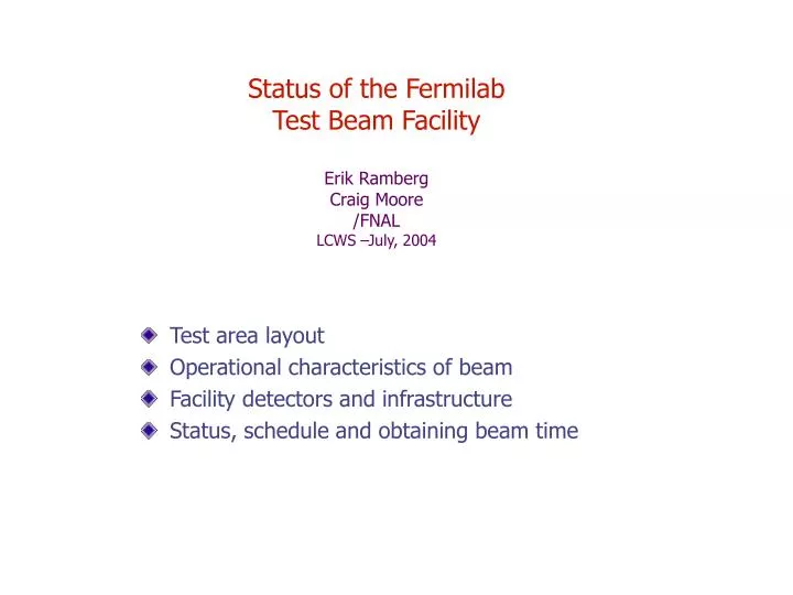
Status of the Fermilab Test Beam Facility Erik Ramberg Craig Moore /FNAL LCWS –July, 2004. Test area layout Operational characteristics of beam Facility detectors and infrastructure Status, schedule and obtaining beam time.

E N D
Status of the Fermilab Test Beam FacilityErik RambergCraig Moore/FNALLCWS –July, 2004 • Test area layout • Operational characteristics of beam • Facility detectors and infrastructure • Status, schedule and obtaining beam time
Web page for MTBF: http://www-ppd.fnal.gov/MTBF-w or Fermilab-at-Work MTBF Test beam coordinator: Erik Ramberg - ramberg@fnal.gov - 630-840-5731
Scale: ~6 m 2 beam enclosures. Eventually, downstream enclosure will be operated independently of upstream. 6 user stations, with a 7th downstream of the beam dump. An experiment can take up more than one station. 2 climate stabilized huts with air conditioning. 2 separate control rooms. Outside gas shed + inside gas delivery system can bring any 2 gases (and exhaust lines) to any of the user areas Lockable work area for small scale staging or repairs.
Split between pbar production and SwitchYard P2,P3 beamlines Transfer Hall Switchyard • ‘SwitchYard 120’ Project: • Delivers Main Injector beam to Meson Detector Building • Runs in conjunction with protons delivered to pbar source (and eventually NUMI) • Spills to SY120 can impact pbar production by no more than 5%
Operational Characteristics • There are several operational modes: • Proton Mode:Tune beamline for 120 GeV protons that get transmitted through the target. Rates at the user area are limited to 1 Mhz. Maximum rates so far are 200 KHz. • Secondary, or ‘Pion’ Mode:Vary the tune of the beamline according to the momentum desired. Maximum momentum is currently 66 GeV, with rates on the order of 10 kHz. Lowest momentum tune is on the order of 3-5 GeV. (See graph of calculated rates) • Muons: By inserting a beam stop upstream, muons of tagged momentum less than 66 GeV can be delivered to both areas. By inserting the beam stop between the two user areas, muons of indeterminate momentum can be delivered to the downstream area. The former mode has not been tested. The latter mode has delivered 100 Hz of muons to the user area. • Electrons: At low momentum (< 5 GeV), the beamline delivers an enhanced electron fraction, at very low rates. There are intermediate target wheels and sweepers to attempt production of an electron beam at higher momentum. This mode has not been tested yet. • Fast extraction delivers from 20-80 buckets of 20 nsec duration. Each bucket has ~ 500 particles. Can insert beamstop to reduce rate to 0.5 particle/bucket. • Resonant extraction delivers ‘smooth’ beam over .6 sec spill. Spill can be made shorter – down to 10 or 20 msec – thus making more intense beam. • Spot sizes can be made as small as 3-5 mm square (with 120 GeV protons) and as large as 5 cm square.
Predicted maximum rates in MT6 as a function of momentum for pions and protons kHz GeV
Chamber at back of MT6B (HV tripped off) SWIC profiles while delivering 120 GeV beam (1 mm wire spacing)
Duty Factor in SY120 • Program planning has determined that SY120 operations will affect pbar production by less than 5% • Standard operation is a single ~600 msec slow spill every minute, but can request more frequent spills for short periods of time • Magnet ramps are set so that, in the future, pbar extraction and resonant extraction could coexist in a single spill. Then the duty factor could be as high as a spill every 2.8 sec. This will probably be tested this summer. 600 ms SY120/ resonant extraction Pbar production/fast extraction
Facility Detectors • Two beamline threshold Cerenkov counters can be operated independently for good particle i.d. (50’ and 80’ long) • Two stations of X,Y silicon strip detectors are installed. • Three 0.5 mm pitch MWPC into DAQ Three 1.0 mm pitch MWPC into the accelerator ACNET control system. • DAQ will be minimum bias triggered during the spill. The data from scintillators, Cerenkov counters, silicon and MWPC go into event buffers. Buffers are read out during and after the spill and this data will be accessible to experimenters.
One of the two beamline Cerenkov counters One of three MWPC stations Remote controlled scintillator finger counters Silicon tracker
T926: Radio Ice Cerenkov Experiment T927: BTeV Pixel Test
List of MTBF Memoranda of Understanding (MOU): T926: RICE- Took data in Feb. - completed T927: BTeV Pixel- Taking data now T930: BTeV Straw- Taking data now T931: BTeV Muon- Install over Summer T932: Diamond Detector- Taking data in Summer T933: BTeV ECAL - Install over Summer T935: BTeV RICH- Install this month and start taking data T936: US/CMS Pixel- Taking data now
Chamber at back of MT6B (HV tripped off) SWIC profiles while delivering 66 GeV beam
Summary of modes achieved • 120 GeV fast spill, 20-84 buckets. • Max rate of 5000 particles/bucket • 120 GeV slow spill, 1-6 turns, 20-84 buckets. 10-400 msec spill. • Max rate of 200,000 particles/spill. • 120 GeV slow spill, 6 turns, 84 buckets, MTSCDC beam stop in. • Max rate of 50 muons/spill in MT6B • 66 GeV slow spill, 6 turns, 84 buckets. Not optimized • Max rate of 4000 particles/spill. • 33 GeV slow spill, 3E11protons in MI • Max rate of 10000 particles/spill. • 16 Gev slow spill, 3E11 protons in MI Max rate of 2300 particles/spill • 8 GeV slow spill, 100 electrons/spill Chamber at back of MT6B (HV tripped off)
Test Beam Duty Cycle • 5% is both a limit and a guarantee • Mixed mode driven by MIPP; at present three pulses gains for everyone • Some problems, hopefully this week we will go into production • We have no experience with NuMI ER/CDM Victoria LCWS