Download
1 / 41
450 likes | 905 Vues
Interaction of Integral Abutment Piling and MSE Walls. Alfredo Arenas and George Filz , Virginia Tech Edward Hoppe, VTRC Keith Weakley, Michael Hall, Kevin Lee, Ashton Lawler, VDOT November 15 th 2010. IAB with MSE Wall. IAB Skew Angle. Telegraph Road, B672 IAB.

E N D
Interaction of Integral Abutment Piling and MSE Walls Alfredo Arenas and George Filz, Virginia Tech Edward Hoppe, VTRC • Keith Weakley, Michael Hall, Kevin Lee, Ashton Lawler, VDOT • November 15th 2010
Objectives and Research Tasks • Objectives • Investigate the interactions between MSE wall systems and integral abutment bridges (IAB) due to thermal expansions and contractions of the bridge deck. • Develop design guidance for IABs with MSE walls. • Tasks • Literature Review • Conduct a national survey of IAB practices • Analyze the usefulness of corrugated steel sleeves around the piles • 100% • 100% • 100%
Research Tasks • Tasks • Analyze the field instrumented IAB by Hassiotis et al (2005) using numerical methods • Perform parameter studies using the validated numerical model • Develop base case model • 25 individual parameter variations • 37 multiple parameter variations • Develop spreadsheet to permit easy use of the results • Prepare VTRC report • 100% • 100% • 100% • 100% • 90% • 90%
Research Results: Corrugated Steel Sleeve Analysis • 2 Load Cases: • Self Weight → Confining Pressure → Displacement up to Failure • Self Weight → Confining Pressure → Cyclic Displacement → Displacement up to Failure
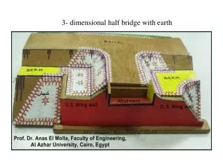
Base Case Model • Model Characteristics • Based on the northern Virginia Integral Bridge Abutment located at the intersection of I-95 and Telegraph Road. • Main characteristics: • 10.5 ft high abutment with dowels • Two lanes with an overall width of 35.8 ft • Five steel girders, 69” high and 166 ft long • Seven HP 10x42 piles at each abutment • Abutment with “wrap around” MSE wall • Main Objectives of the Base Case Model • Establish a basis for comparison • Demonstrate the response and interaction of principal bridge components due to cyclic thermal loads.
Research Results: Validation Elevation 58 m (2/3 abutment height) Elevation 56.5 m (1/5 abutment height) Flac3D Field Measurements from Hassiotis et al. 2005
Parametric Variation • Models • 25 single parameter variation models • Input parameters • Abutment design: Dowel, laminated pad, and solid • Abutment – MSE wall distance • Thermal displacement magnitude • EPS behind abutment and front MSE wall • Foundation material • MSE wall and abutment heights • Pile size and orientation • Skew angle • Reinforcing strips behind the abutment
Parametric Variation • Main Objectives of the Single Parameter Variation Models • Identify which input parameters are relevant to the bridge response • Determine which input parameters influence the response of which output parameters • Quantify the impact of design input parameters on the bridge response
Research Results: Parametric Study • Key Findings • The distance between the pile centerline and the back of the MSE wall doesn’t affect moment and shear forces of dowels and piles, but it does affect the strip tensile force and MSE wall earth pressures. • Shear forces and moments in the dowels and piles due to thermal displacement are, on average, 20 times larger than those imposed by gravity (dead) loads. • For bridges with large skew angles, displacements in the transverse direction can reach about the same magnitudes as for the longitudinal displacement.
Research Results: Parametric Study • Key Findings • Peak tensile forces in the reinforcing strips near the abutment can increase up to 110% due to thermal displacements. Depending on the bridge details, designs may need to take this into account. • The use of 3” of EPS behind the MSE wall has marginal benefits on the effects of thermal displacements on the MSE wall, but it can significantly reduce the strip tensile force and pressure on the MSE wall due to gravity (dead) loads. • Thermal displacements only affect the upper quarter of the MSE wall.
Research Results: Parametric Study • Key Findings • Pile axial load is not significantly affected by thermal displacements. • EPS behind the abutment reduces lateral earth pressures by a factor of 9 for the upper portion of the abutment and by a factor of 20 for the lower portion of the abutment, according to the numerical analyses. • Skew angle progressively increases pile cap fixity, producing a reversal in the pile moments. • Skew angle affects the distribution and magnitude of the earth pressure behind the abutment.
Multiple Parameter Variation • Models • 37 multiple parameter variation models • Models combine from 2 to 5 input parameters • Main Objective of the Multiple Variation Models • Determine whether the influence of two or more parameters is multiplicative or additive, or whether their effects should be combined in some other way
IBA v2 Spreadsheet • Objective • Implement a simple and efficient spreadsheet to compute loads on IBAs due to thermal displacements. • Method • Categorize results in groups of output parameters, each controlled by the same group of input parameters • Use polynomial equations to fit the numerical data, and implement them in the spreadsheet
IBA v2 Spreadsheet • Output Parameters • Plot of thermal displacement • EPS thickness according to VTRC procedure • Maximum moments in dowels and piles, in longitudinal and transverse directions • Maximum shear forces in dowels and piles, in longitudinal and transverse directions • Maximum axial forces in dowels and piles • Maximum earth pressures at two elevations behind abutments, at acute and obtuse corners • MSE wall earth pressures • MSE wall strip tensile forces, peak and connection values • Transverse displacement
IBA v2 Spreadsheet: Example • Bridge Specification • 600 ft long IAB • Annual ΔT 100˚F • Seven piles oriented for weak moment • Pile cap connected to the abutment using 32 dowels • Abutment height is 10 ft • Use Spreadsheet to Find Reinforcing Strip Tension for These Cases: • Piles: 10x42, 12x63, and 14x73 • Distance between abutment and MSE wall:4.5 ft to 0.5 ft.
IBA v2 Spreadsheet: Example Increment in Reinforcing Strip Tensile Force Due to Thermal Displacement
IBA v2 Spreadsheet: Example Increment in Reinforcing Strip Tensile Force Due to Thermal Displacement
IBA v2 Spreadsheet: Example Increment in Reinforcing Strip Tensile Force Due to Thermal Displacement
IBA v2 Spreadsheet: Example Increment in Reinforcing Strip Tensile Force Due to Thermal Displacement
Interaction of Integral Abutment Piling and MSE WallsQuestions?