Download
1 / 31
570 likes | 1.34k Vues
Satellite Link Design. Content . Design of the Satellite Links Link Budget and their Interpretation. Introduction. A satellite link is defined as an Earth station - satellite - Earth station connection. The Earth station - satellite segment is called the uplink

E N D
Content • Design of the Satellite Links • Link Budget and their Interpretation
Introduction • A satellite link is defined as an Earth station - satellite - Earth station connection. • The Earth station - satellite segment is called the uplink • The satellite - Earth station segment is called the downlink
Introduction The Earth station design consists of, • The Transmission Link Design or the Link Budget, • the Transmission System Design. • The Link Budget establishes the resources needed for a given service to achieve the performance objectives
Design of the Satellite Link • The satellite link is probably the most basic in microwave communications since a line-of-sight path typically exists between the Earth and space. • This means that an imaginary line extending between the transmitting or receiving Earth station and the satellite antenna passes only through the atmosphere and not ground obstacles.
Design of the Satellite Link • Free-space attenuation is determined by the inverse square law, which states that the power received is inversely proportional to the square of the distance. • There are, however, a number of additional effects that produce a significant amount of degradation and time variation. • These include rain, terrain effects such as absorption by trees and walls, and some less-obvious impairment produced by unstable conditions of the air and ionosphere.
Design of the Satellite Link • It is the job of the communication engineer to identify all of the significant contributions to performance and make sure that they are properly taken into account. • The required factors include the performance of the satellite itself, • The configuration and performance of the uplink and downlink Earth stations, and • The impact of the propagation medium in the frequency band of interest.
Design of the Satellite Link • The RF carrier in any microwave communications link begins at the transmitting electronics and propagates from the transmitting antenna through the medium of free space and absorptive atmosphere to the receiving antenna, where it is recovered by the receiving electronics. • The carrier is modulated by a baseband signal that transfers information for the particular application. • The first step in designing the microwave link is to identify the overall requirements and the critical components that determine performance. • For this purpose, we use the basic arrangement of the link shown in Figure.
Design of the Satellite Link • Bidirectional (duplex) communication occurs with a separate transmission from each Earth station. • Due to the analog nature of the radio frequency link, each element contributes a gain or loss to the link and may add noise and interference as well.
Design of the Satellite Link • The result in the overall performance is presented in terms of the ratio of carrier power to noise and, ultimately, information quality • Any uncertainty can be covered by providing an appropriate amount of link margin, which is over and above the C/N needed to deal with propagation effects and nonlinearity in the Earth stations and satellite repeater.
Satellite Link Design The four factors related to satellite system design: 1.The weight of satellite 2.The choice frequency band 3.Atmospheric propagation effects 4.Multiple access technique • The major frequency bands are 6/4 GHz, 14/11 GHz and 30/20 GHz (Uplink/Downlink) • At geostationary orbit there is already satellites using both 6/4 and 14/11 GHz every 2˚(minimum space to avoid interference from uplink earth stations)
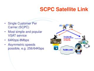
LINK BUDGET The link budget determines the antenna size to deploy, • Power requirements, • link availability, • bit error rate, • overall customer satisfaction with the satellite service. • A link budget is a tabular method for evaluating the power received and the noise ratio in a radio link . • It simplifies C/N ratio calculations • The link budget must be calculated for an individual transponder, and must be recalculated for each of the individual links
LINK BUDGET The satellite link is composed primarily of three segments: (i) the transmitting Earth station and the uplink media; (ii) the satellite; and (iii) the downlink media and the receiving Earth station. • The carrier level received at the end of the link is a straightforward addition of the losses and gains in the path between transmitting and receiving Earth stations.
LINK BUDGETS • C/N ratio calculation is simplified by the use of link budgets • Evaluation of the received power and noise power in radio link • the link budget must be calculated for individual transponder and for each link • When a bent pipe transponder is used the uplink and down link C/N ratios must be combined to give an overall C/N
Link Budget Example • Satellite application engineers need to assess and allocate performance for each source of gain and loss. • The link budget is the most effective means since it can address and display all of the components of the power balance equation, expressed in decibels. • In the past, each engineer was free to create a personalized methodology and format for their own link budgets. • This worked adequately as long as the same person continued to do the work. • Problems arose, however, when link budgets were exchanged between engineers, as formats and assumptions can vary. • A standardized link budget software tool should be used that performs all of the relevant calculations and presents the results in a clear and complete manner.
Link Budget Example • We will now evaluate a specific example using a simplified link budget containing the primary contributors. • This will provide a typical format and some guidelines for a practical approach. • Separate uplink and downlink budgets are provided; our evaluation of the total end-to-end link presumes the use of a bent-pipe repeater. • This is one that transfers both carrier and noise from the uplink to the downlink, with only a frequency translation and amplification. • The three constituents are often shown in a single table, but dividing them should make the development of the process clearer for readers. • The detailed engineering comes into play with the development of each entry of the table. • Several of the entries are calculated using straightforward mathematical equations; others must be obtained through actual measurements or at least estimates thereof.
Link Budget Example • This particular example is for a C-band digital video link at 40 Mbps, which is capable of transmitting 8 to 12 TV channels using the Motion Picture Experts Group 2 (MPEG 2) standard.
Link Budget Example:Downlink Budget The following Table 2.3 presents the downlink budget in a manner that identifies • the characteristics of the satellite transmitter • and antenna, • the path, • the receiving antenna, • and the expected performance of the Earth station receiver. • It contains the elements that select the desired radio signal (i.e., the carrier) and demodulates the useful information (i.e., the digital baseband containing the MPEG 2 “transport” bit stream). • Once converted back to baseband, the transmission can be applied to other processes, such as de-multiplexing, decryption, and digital-to-analog conversion (D/A conversion).
Link Budget Example:Downlink Budget • Each of the link parameters relates to a specific piece of hardware or some property of the microwave path between space and ground. • A good way to develop the link budget is to prepare it with a spreadsheet program. • This permits the designer to include the various formulas directly in the budget, thus avoiding the problem of external calculation or the potential for arithmetic error • Commercial link budget software, such as SatMaster Pro from Arrowe Technical Services, does the same job but in a standardized fashion.
Satellite link design -Uplink • Uplink design is easier than the down link in many cases • earth station could use higher power transmitters • Earth station transmitter power is set by the power level required at the input to the transporter, either • a specific flux density is required at the satellite • a specific power level is required at the input to the transporter • analysis of the uplink requires calculation of the power level at the input to the transponder so that uplink C/N ratio can be found • With small-diameter earth stations, a higher power earth station transmitter is required to achieve a similar satellite EIRP. • interference to other satellites rises due to wider beam of small antenna • Uplink power control can be used against uplink rain attenuation
C/N [C/N0]D = [EIRP]D + [G/T]D - [LOSSES]D – [k] [C/N0]U = [EIRP]U + [G/T]U - [LOSSES]U – [k]
Link Budget Example:Overall Link Budget • The last step in link budgeting for a bent-pipe repeater is to combine the two link performances and compare the result against a minimum requirement—also called the threshold. • Table 2.5 presents a detailed evaluation of the overall link under the conditions of line-of-sight propagation in clear sky. • We have included an allocation for interference coming from sources such as a cross-polarized transponder and adjacent satellites. • This type of entry is necessary because all operating satellite networks are exposed to one or more sources of interference. • The bottom line represents the margin that is available to counter rain attenuation and any other losses that were not included in the link budgets. • Alternatively, rain margin can be allocated separately to the uplink and downlink, with the combined availability value being the arithmetic product of the two as a decimal value (e.g., if the uplink and downlink were each 99.9%, then the combined availability is 0.999 × 0.999 = 0.998 or 99.8%).
SATELLITE LINK DESIGN METHODOLOGY The design methodology for a one-way satellite communication link can be summarized into the following steps. The return link follows the same procedure. • Step 1. Frequency band determination. • Step 2. Satellite communication parameters determination. Make informed guesses for unknown values. • Step 3. Earth station parameter determination; both uplink and downlink. • Step 4. Establish uplink budget and a transponder noise power budget to find (C/N)up in the transponder • Step 5. Determine transponder output power from its gain or output backoff.
SATELLITE LINK DESIGN METHODOLOGY • Step 6. Establish a downlink power and noise budget for the receiving earth station • Step 7. Calculate (C/N)down and (C/N)u for a station at the outermost contour of the satellite footprint. • Step 8. Calculate SNR/BER in the baseband channel. • Step 9. Determine the link margin. • Step 10. Do a comparative analysis of the result vis-à-vis the specification requirements.
SATELLITE LINK DESIGN METHODOLOGY • Step 11. Tweak system parameters to obtain acceptable (C/N)0 /SNR/BER values. • Step 12. Propagation condition determination. • Step 13. Uplink and downlink unavailability estimation. • Step 14. Redesign system by changing some parameters if the link margins are inadequate. • Step 15. Are gotten parameters reasonable? Is design financially feasible? • Step 16. If YES on both counts in step 15, then satellite link design is successful – Stop. • Step 17. If NO on either (or both) counts in step 15, then satellite link design is unsuccessful – Go to step 1.