Download
1 / 47
3.16k likes | 9.26k Vues
Chapter 4: Heat Transfer from Extended Surfaces. 4.1 …………. Introduction and Types of Fins 4.2 …………. Governing Equation of Fin 4.3 …………. Heat Dissipation through Rectangular Fin 4.4 …………. Heat Dissipation from Infinitely Long Fin 4.5 …………. Heat Dissipation from a Fin Insulated at the Tip

E N D
Chapter 4: Heat Transfer from Extended Surfaces 4.1 …………. Introduction and Types of Fins 4.2 …………. Governing Equation of Fin 4.3 …………. Heat Dissipation through Rectangular Fin 4.4 …………. Heat Dissipation from Infinitely Long Fin 4.5 …………. Heat Dissipation from a Fin Insulated at the Tip 4.6 …………. Heat Dissipation from a Fin Losing Heat at a Tip 4.7 …………. Fin Efficiency and Effectiveness 4.8 …………. Estimation of error in temperature measurement in a thermometer well
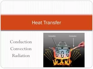
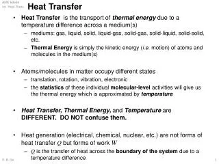
4.1 … Introduction and Types of Fins • Convection: Heat transfer between a solid surface and a moving fluid is governed by the Newton’s cooling law: q = hA(Ts-T). Therefore, to increase the convective heat transfer, one can • Increase the temperature difference (Ts-T) between the surface and the fluid. • Increase the convection coefficient h. This can be accomplished by increasing the fluid flow over the surface since h is a function of the flow velocity and the higher the velocity, the higher the h. Example: a cooling fan. • Increase the contact surface area A. Example: a heat sink with fins. • An extended surface (also know as a combined conduction-convection system or a fin) is a solid within which heat transfer by conduction is assumed to be one dimensional, while heat is also transferred by convection (and/or radiation) from the surface in a direction transverse to that of conduction.
Introduction and Types of Fins (continue….) • The term extended surface (Fin) is commonly used in reference to a solid that experiences energy transfer by conduction within its boundaries, as well as energy transfer by convection (and/or radiation) between its boundaries and the surroundings. • Extended surfaces may exist in many situations but are commonly used as fins to enhance heat transfer by increasing the surface area available for convection (and/or radiation). • Note: They are particularly beneficial when h is small, as for a gas and natural convection.
Introduction and Types of Fins (continue….) • APPLICATIONS: • the arrangement for cooling engine heads on motorcycles and lawn-mowers or • for cooling electric power transformers • the tubes with attached fins used to promote heat exchange between air and the working fluid of an air conditioner. Types of Fins Straight fin of uniform cross section Straight fin of non uniform cross section Annular fin Pin fin
4.2 … Governing Equation of Fin Ac(x) dAs(x) dx dx x Tb T∞, h
Governing Equation of Fin (continue….) Assumptions • Heat transfer is assumed to be in only one dimensional i.e., in the longitudinal (x) direction, even though conduction within the fin is actually two dimensional. • The rate at which the energy is convected to the fluid from any point on the fin surface must be balanced by the rate at which the energy reaches that point due to conduction in the transverse ( y,z ) direction. However, in practice the fin is thin and temperature changes in the longitudinal direction are much larger than those in the transverse direction. • Steady state conditions are assumed. • Thermal conductivity is assumed to be constant . • Radiation from the surface is assumed to be negligible . • Convection heat transfer coefficient is assumed to be uniform over the surface.
T(x) T∞, h Ac(x) dAs(x) x dx
P dAs dx Fins of Uniform Cross-Sectional Area L P: fin perimeter Tb Ac(x) = constant, and dAs = Pdx Ac x
where excess temperature :q(x) = T(x) - T∞ L Tb T(x) dx x boundary conditions at x = 0:
L Tb T(x) at x = L: ---- 3 cases dx x 1) very long fin (L → ∞): 2) convection tip: 3) negligible heat loss: adiabatic tip
Temperature distribution 1) long fin: 2) convection tip: 3) adiabatic tip:
or Total heat loss by the fin L 1) long fin: Tb P Ac 2) convection tip: dAs dx x 3) adiabatic tip:
Temperature distribution for fins of different configurations Note: This table is adopted from Introduction to Heat Transfer by Frank Incropera and David DeWitt
4.7 … Fin Efficiency and Effectiveness How effective a fin can enhance heat transfer is characterized by the fin effectiveness f: Ratio of fin heat transfer and the heat transfer without the fin. For an adiabatic fin:
Fin Effectiveness (contd...) • To increase f, the fin’s material should have higher thermal conductivity, k. • It seems to be counterintuitive that the lower convection coefficient, h, the higher f. But it is not because if h is very high, it is not necessary to enhance heat transfer by adding heat fins. Therefore, heat fins are more effective if h is low. Observation: If fins are to be used on surfaces separating gas and liquid. Fins are usually placed on the gas side. (Why?)
Tb Tb x x Ideal situation Realsituation Fin Efficiency The fin efficiency is defined as the ratio of the energy transferred through a real fin to that transferred through an ideal fin. An ideal fin is thought to be one made of a perfect or infinite conductor material. A perfect conductor has an infinite thermal conductivity so that the entire fin is at the base material temperature.
L1 t T1 T Tb T2 T Tb T2 T1 R1=L1/(k1A) Thermal Resistance Concept A=Ab+NAb,f Rb= t/(kbA)
4.8 … Estimation of Error in Temperature Measurement in a Thermometer Well A thermometer well is defined as a small tube welded radially into a pipeline through which a fluid whose temperature is to be measured is flowing. Let, l= length of the well/tube d= internal diameter of well/tube δ= thickness of well/tube tf= temperature of the fluid flowing through pipe to= temperature of the pipe=wall ta= ambient temperature tl= temperature at bottom of well • When tf> ta , the heat flows from fluid to towards the tube wall along the well. The temperature at the bottom of well becomes colder than fluid flowing around, obviously the temperature shown by the thermometer will not be the temperature of the fluid. • This error may be calculated by assuming the well to be a spine protruding from the wall of a pipe in which fluid is flowing.
Note: Assumption for simplicity, that there is no flow of heat from tip (i.e. insulated tip) Temperature distribution at any distance x, At x=l, = Thermometric Error Perimeter Cross section Area Thus, the temperature measured by the thermometer is not affected by the diameter of the well. From previous equation, observed that in order to reduce the temperature measurement error, ml should be large necessitating the following: (i) Large value of h, (ii)Small value of k & (iii) Long and thin well
Definition: An extended surface (also know as a combinedconduction-convection system or a fin) is a solid within which heat transfer by conduction is assumed to be one dimensional, while heat is also transferred by convection from the surface Extended surfaces may exist in many situations but are commonly used as fins to enhanceheat transfer by increasing the surfacearea available for convection.
They are particularly beneficial when heat transfer coefficient (h) is small as for a gas and natural convection. Some typical fin configurations: Straight fin of non uniform cross section Straight fin of uniform cross section Annular fin Pin fin
Ac(x) dAs(x) dx dx Equation for Extended Surfaces x Tb T∞, h
T(x) T∞, h Ac(x) dAs(x) x dx
P dAs dx Fins of Uniform Cross-Sectional Area L P: fin perimeter Tb Ac(x) = constant, and dAs = Pdx Ac x
where excess temperature: q(x) = T(x) - T∞ L Tb T(x) dx x boundary conditions at x = 0:
Boundary Conditions Several boundary conditions are typically employed: • At the fin base • Specified temperatureboundary condition, expressed as: q(0)= qb=Tb-T∞ • At the fin tip • Specified temperature • Infinitely Long Fin • Adiabatic tip • Convection (and combined convection). Adapted from Heat and Mass Transfer – A Practical Approach, Y.A. Cengel, Third Edition, McGraw Hill 2007.
Temperature distribution for fins of different configurations
Heat transfer rate from the fin of base area Ab Heat transfer rate from the surface of area Ab Fin Effectiveness Adapted from Heat and Mass Transfer – A Practical Approach, Y.A. Cengel, Third Edition, McGraw Hill 2007. • The performance of the fins is judged on the basis of the enhancement in heat transfer relative to the no-fin case. • The performance of fins is expressed in terms of the fin effectiveness efin defined as
T Tb Fin Design Total heat loss: qf=Mtanh(mL) for an adiabatic fin, or qf=Mtanh(mLC) if there is convective heat transfer at the tip
Tb x x Fin Efficiency (contd…) For infinite k T(x)=Tb, the heattransfer is maximum T(x)<Tb for heat transfer to take place Ideal heat transfer qmax Total fin heat transfer qf Ideal situation Real situation
Fin Efficiency (cont.) Use an adiabatic rectangular fin as an example:
qf qb Overall Fin Efficiency Overall fin efficiency for an array of fins: Define terms: Ab: base area exposed to coolant Af: surface area of a single fin At: total area including base area and total finned surface, At=Ab+NAf N: total number of fins
Heat Transfer through Extended Surface or Fins Prepared by: Nimesh Gajjar Bare surface Finned surface
Definition: An extended surface (also know as a combinedconduction-convection system or a fin) is a solid within which heat transfer by conduction is assumed to be one dimensional, while heat is also transferred by convection from the surface Extended surfaces may exist in many situations but are commonly used as fins to enhanceheat transfer by increasing the surfacearea available for convection.
They are particularly beneficial when heat transfer coefficient (h) is small as for a gas and natural convection. Some typical fin configurations: Straight fin of non uniform cross section Straight fin of uniform cross section Annular fin Pin fin
Ac(x) dAs(x) dx dx Equation for Extended Surfaces x Tb T∞, h
T(x) T∞, h Ac(x) dAs(x) x dx
P dAs dx Fins of Uniform Cross-Sectional Area L P: fin perimeter Tb Ac(x) = constant, and dAs = Pdx Ac x
where excess temperature: q(x) = T(x) - T∞ L Tb T(x) dx x boundary conditions at x = 0:
Boundary Conditions Several boundary conditions are typically employed: • At the fin base • Specified temperatureboundary condition, expressed as: q(0)= qb=Tb-T∞ • At the fin tip • Specified temperature • Infinitely Long Fin • Adiabatic tip • Convection (and combined convection). Adapted from Heat and Mass Transfer – A Practical Approach, Y.A. Cengel, Third Edition, McGraw Hill 2007.