Download
1 / 55
550 likes | 721 Vues
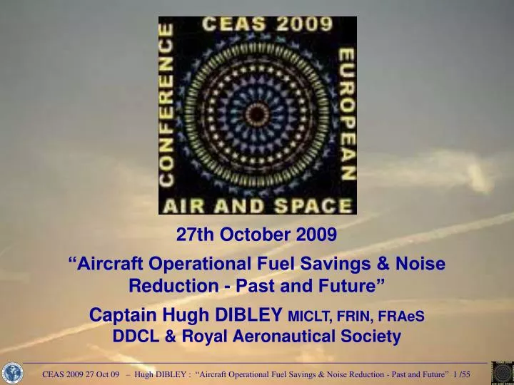
27th October 2009 “Aircraft Operational Fuel Savings & Noise Reduction - Past and Future” Captain Hugh DIBLEY MICLT, FRIN, FRAeS DDCL & Royal Aeronautical Society. Lecture Summary Simplified Aircraft Flight Profile – for a Single Aircraft

E N D
27th October 2009“Aircraft Operational Fuel Savings & Noise Reduction - Past and Future”Captain Hugh DIBLEY MICLT, FRIN, FRAeSDDCL & Royal Aeronautical Society
Lecture Summary • Simplified Aircraft Flight Profile – for a Single Aircraft • Efficiency Loss as ATC must Separate Aircraft then Merge to Land • Pre-Flight Planning – Cost of Carrying Extra Fuel on the Sector • Departure Noise Abatement Procedures • Cruise - Fuel Savings & Crew Situational Awareness • Descent – Large opportunity for Fuel Savings • Approach – Large opportunity for Fuel Savings & Noise Reduction • Steep Approaches – to reduce noise? • Crews’ Ability to Save Fuel/Time by Choosing Approach & Runway • Past Examples of Operational Fuel Savings • Possible Future Operational Fuel Savings • “Future” ATM Fuel Savings Being Achieved NOW – USA • “Future” ATM Fuel Savings Being Achieved NOW - Europe • Accidents which Need NOT have Happened • Conclusion
Simplified Aircraft Flight Profile – for a Single Aircraft Single aircraft Efficiency is reduced by the need for ATC to separate aircraft to avoid conflicts then merge again for landing
ATC Sectors Los Angeles, USA ATC Sectors in South East England, UK 2. Efficiency Loss as ATC must Separate Aircraft then Merge to Land ATC often have to take aircraft away from their optimum route and altitude to separate aircraft safely. The distance between aircraft, and loss of efficiency, depends upon the navigational accuracy of the total system – could vary from 3 miles under radar to 120 miles en-route. Latest navigation systems can reduce en-route space to 5 miles. ATC is split into separate centres, sometimes determined nationally, and liaison between centres can reduce efficiency. During descent aircraft may have to cross points between centres at specific altitudes thus flying level rather than following an efficient continuous descent with idle thrust.
2. Efficiency Loss as ATC must Separate Aircraft then Merge to Land As aircraft approach their destination, ATC must merge aircraft into a stream to the runway to achieve the most efficient landing rate. At present this is usually achieved by ATC giving aircraft headings and speeds to fly at low levels which stretch the approach path while aircraft are placed in sequence at the required spacing for the type causing extra fuel consumption and noise over the ground. New Air Traffic Management Systems will merge aircraft into their landing sequence earlier in the flight, and allow more efficient descents with idle thrust leading to quieter Constant Descent Approaches with no periods of level flight. The complexity of the process to merge traffic efficiently can be seen from the aircraft tracks into Schiphol airport at Amsterdam and simulations of the Paris arrival routes. Simulation of Paris Arrivals
3 Pre-Flight Planning – Cost of carrying extra fuel Carrying extra fuel over the minimum flight plan fuel always involves as penalty due to the extra weight burnt at 3% per hour. The actual cost of extra fuel depends on the relative cost of fuel between the departure and destination airfields. If the fuel is cheap enough at the departure airfield it can be worthwhile carrying/tankering extra fuel into the destination. However the effect of the extra weight on the aircraft must be considered – extra landing distance, possible extra brake wear and use of reverse thrust, reduced maximum cruise altitude, etc. This decision is best made by the crew on the day who need to know the cost of extra fuel for the most economic judgement. For example: LHR-BRU Save $1/tonne – not worth tanking for fuel price alone. HKG-NGO Save $127/tonne – definitely worth tankering. HKG-DEL Cost £1/tonne – extra fuel could be cheap insurance if delays en route were likely. NGO-HKG Cost £206 – cost of extra fuel prohibitive. Many companies do not publish Fuel Price Differentials but just tell crews when to “tanker” fuel, which may not be efficient.
4. Noise Abatement Departure Procedures 1 & 2 Early turbojet powered aircraft were extremely noisy on takeoff so had to climb steeply to 3,000ft before accelerating to retract flaps and climb at the most efficient speed, shown as NADP 1 in red. Later fan jet engines with colder/slower exhaust streams made less noise so could accelerate sooner and climb more efficiently shown as NADP 2 in green. Noise close to the airport could be increased but was less than from turbojet aircraft, and noise further out is reduced as the aircraft is higher than with NADP 1.
4. Noise Abatement Departure Procedures 1 & 2 The noise foot print from current large fan jet aircraft is some 75% less than from the early fan jet aircraft, therefore NADP 2 can be used at most airports without causing significant noise disturbance close to the runway. Yet some states specify that the less efficient NADP 1 be followed at airports where urban noise reduction is not a factor. This is causing significant amounts of unnecessary amounts of extra fuel to be burnt and emissions released into the atmosphere at low level.
A380 Optimised Engine Thrust & Climb Profile A380 airframe & engine designed to minimize noise 4. A380 Aircraft & Engines Optimised for Low Departure Noise Minimising aircraft departure noise is considered to be a critical factor in aircraft design. Rolls-Royce increased the fan size of the Trent 900 for the Airbus A380 to comply with the London Heathrow airport departure noise limits at the highest takeoff weight. Airbus optimised the low speed performance of the aircraft and engine nacelle design and minimised the airframe noise to make the A380 currently the quietest large jet aircraft. After takeoff engine thrust is selected automatically for minimum noise on the designed climb profile which produces the best compromise between climb rate and acceleration as the aircraft gains altitude to create the minimum overall noise disturbance.
5. Cruise - Fuel Savings by Making Maximum Use of Winds The flight profile must make maximum benefit of the considerable energy in the atmosphere. The example shows times when the wind component over Western Europe changed by 220 kts. Flight planning systems are fed with winds direct from the forecast weather models which can be updated by information from aircraft in flight and fed back by AMDAR. Aircraft Meteorological DAta Relay was started by the Australian Bureau of Meteorology in the mid 1980s
5. Cruise - Fuel Savings by Making Maximum Use of Winds EUMetNet-AMDAR became part of EUCOS observing system headed by the Swedish Met Service (SMHI) to manage the collective resources of the 10 contributing National Met Services to deliver the best available quality of meteorological information Wind, temperature & possibly humidity data from aircraft in flight – currently Air France-KLM, British Airways, Finnair, Lufthansa & SAS - is downlinked via the ARINC/SITA networks. E-AMDAR uses the data to update the weather models which are sent to users including aircraft in flight. However changing routes to take advantage of strong winds are not always possible due to military or political reasons. Some oceanic routes still use fixed tracks with large separation standards which can be reduced in future using improved ATM systems.
5. Cruise - Fuel Savings by Making Maximum Use of Winds Examples of Oceanic Routes – Some fixed, others are variable calculated by the ATC to produce Organised Track Systems or by individual operators for their Preferred Routes
5. Cruise - Fuel Savings by Making Maximum Use of Winds An example showing an advantage of future ATM systems – Separation across the Gulf of Mexico can be reduced from 15minutes/120 nautical miles to 5 nm after ADS-B (Automatic Dependent Surveillance-Broadcast) has been enabled which links aircraft FMS information with the Air Traffic Centres on the ground
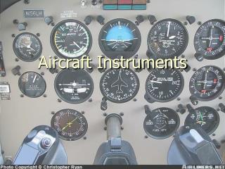
Engine Out Altitudes may only be available on graphs Cruise Speed & Fuel Consumption Relationship 5. Cruise – Crews Need to be Aware of Aircraft Performance Crews should be have a good knowledge of the performance of their aircraft such as: Optimum speeds for minimum cost, minimum fuel, etc and the penalties for flying away from the normal/recommended speeds. Maximum altitudes for the aircraft weight and air temperature – All engines (provided by the FMS) and if limited by engine thrust of airframe buffet (not shown by FMS). Engine(s) Out altitude which may not be shown by the FMS with all engines running and be only available from graphs which are difficult to read quickly. Crews have climbed the latest aircraft with modern FMS above the maximum recommended altitude and had to descend again. Some aircraft have become upset with total loss of control.
5. Cruise – Crews Need to be Aware of Aircraft Performance Table showing Boeing 747 Freighter Performance. All Engines and Engine Out information is quickly available for use after loss of the FMS or flight instruments.
5. Cruise – Crews Need to be Aware of Aircraft Performance Table of Airbus A320 All Engines and Engine Out information showing the overall capability of the aircraft – better than from an FMS. Data is available after system failures.
6. Descent – Large opportunity for Fuel Savings – or Wastage THERE IS NO TRADE BETWEEN FUEL & TIME DUE TO A POOR DESCENT Summary of Penalties Cause by Poorly Executed Descents: (Written in 1973 – some of us were worried about the environment then….)
6. Descent – Large opportunity for Fuel Savings – or Wastage Reduction of True Air Speed at Low Altitude at the same Indicated Air Speed causes increase in fuel consumption and flight time Descending early wastes fuel and time, can expose aircraft to icing conditions and more aircraft traffic, makes more noise, etc
6. Descent – Large opportunity for Fuel Savings – or Wastage NASA B737 Descent Trials showed that a typically flown profile in line operation which descended early burnt 40% more fuel than the NASA 737 while taking the same time.
6. Descent – Large opportunity for Fuel Savings – or Wastage Circular slide rule primarily designed to help crews follow an efficient flight idle descent profile to comply with an ATC clearance such as to cross 23 DME XYZ at 8,000ft at 250kts. Direct DME-Altitude checks are available throughout to verify on the profile. A fixed gradient of 400ft per mile above 10,000ft is suitable for IAS of 300-340kts according to aircraft weight, and 300ft per mile below 10,000ft is suitable for 250kts IAS. Checking the profile mentally, normally by 300ft per mile, requires regular computation of an equation, such as at 50 DME: (50-8-23) x 300 = 5,700 + 8,000 = 13,700ft In a survey BOAC B747 pilots estimated their efficiency was improved by at least 10 miles when using the computer, covering the cost of the 2 provided on each aircraft in 1 flight. Besides minimising fuel burn and noise, following this profile improves safety by keeping the aircraft well clear of the ground into nearly all airfields.
6. Descent – Large opportunity for Fuel Savings – or Wastage United Airlines nearly bought the circular computer but while the fixed gradient was suitable 747s & DC10s, DC9s found it too steep and B727s too shallow for their high speeds. This linear computer has the altitude and sink rate on an elastic scale which can set gradients from 250ft per mile for slow speed descents or when in a tailwind up to 600ft per mile suitable for high speeds on a light aircraft into headwinds of 200kts. Could provide smoother descents than A340 FMGEC but not worth the effort for reduced engine changes. Aircraft FMS now fly efficient descents, but if taken off the planned route by ATC pilots can be back to calculating the best profile using mental arithmetic.
7. Approach – Critical for Fuel Savings & Noise Reduction Approach is the phase of flight after descent when the aircraft is decelerated and configured by extending flaps for the final approach. Ideally it is a short period of continuous descent. If ATC may need to give headings and speeds while aircraft are merged into a landing stream, when flaps and landing gear must be extended as late as possible to minimise the extra fuel burnt. The baseline of the table giving comparative fuel consumption is when cruising at FL370/37,000ft. Minimum fuel is consumed while descending which shows that long slow descents with idle thrust are the most fuel efficient. Maximum noise and fuel consumption, 400% more than at cruise altitude, is when flying level with flaps and gear extended (500% on a B747), but reduced when descending on the final glidepath even with the extra drag of full landing flap. This demonstrates that level flight should be resisted if possible and that level flight with flaps and gear extended should avoided at all costs. Baseline Cruising at 37,000ft Maximum Fuel Consumption Minimum Fuel Consumption
7. Approach – Critical for Fuel Savings & Noise Reduction This shows that city life need not be disturbed significantly if aircraft are flown level with minimum flap setting above 3,000ft, preferably at least 5,000ft, before descending on the glideslope to the runway with gear up until about 1,500ft to be established for landing by 1,000ft. (On Airbus aircraft the gear can extended at 800ft, like the Space Shuttle, but this is not the approved procedure.)
7. Approach – Critical for Fuel Savings & Noise Reduction One operator into London Heathrow required the flaps and gear extension to be confirmed in the Initial Approach Checklist which was completed when leaving the entry points to the London area, so the aircraft could fly with the gear extended for up to 60 miles. With the extra drag of the gear and flaps the aircraft would descend steeply and then fly at low altitude across central London making conversation impossible when over flying. Aircraft noise in central London was so disturbing that the Maplin enquiry investigated if the third London airport should be built 100km East of London on the Essex/North Sea coast.
7. Approach – Critical for Fuel Savings & Noise Reduction To try and reduce the extreme levels of noise over central London this article was published in the GAPAN Journal of March 1974 (Appendix A in the CEAS paper and at www.Dibley.eu.com.) Suggesting that crews should ideally fly a continuous descent from the entry point to intercept the runway glideslope and extend the landing at about 1,500ft to be stabilised in the landing configuration by 1,000ft. The idea was accepted by UK NATS and after input from Lufthansa who were proposing their similar Managed Drag Procedure, Constant Descent Approaches were started into LHR in 1975. DMEs were installed to give crews continuous distance to the runway paid for by the Department of Trade who was responsible for Noise Abatement. However CDAs into LHR were not implemented as well as hoped as the procedure has yet to be included in the manufacturers operating manuals. While local operators are proficient less regular visitors will tend to descent early to intercept the glideslope from below. Similar CDAs can be flown into airports like JFK - immediately reducing noise on the approach.
7. Approach – Critical for Fuel Savings & Noise Reduction The type of CDA introduced into London and the Netherlands can give worthwhile noise reductions from 10 to 25 miles from the runway with no additional technology, and are being implemented in other airports such as Sacramento. However at busy airports merging aircraft into an efficient sequence for the approach can be more difficult with aircraft trying to fly CDAs. Future ATM systems due in service by about 2010 will allow efficient CDAs from cruise altitude, but procedures using parts of this system are already operating in some areas as described later. UPS have been integrating their own aircraft flying CDAs into Louisville, which is possible because UPS is the only operator there at night. Similarly because of their relatively low level of traffic the Swedish aviation authority LFV have been developing “Green” 4D trajectories flying CDAs into Stockholm Arlanda, both locally from and across the Atlantic. However crews can still make savings using their own initiative.
8. Crews Can Save Fuel/Time by Choosing Approach/Runway Approach tracks into busy airports can be structured with a long lead in for bad weather, and some are flown automatically to follow agreed noise routes. When traffic and weather permits, crews should be allowed to fly shorter visual approaches
8. Save Fuel/Time Flying Constant Angle VOR-DME Approach Advantage of Being Able to Fly a Constant Angle VOR-DME Approach Using DME-Altitude Table To Confirm On Profile to the Runway Nairobi Kenya – Main ILS Precision Approach is to Runway 06, after which a 10 minute Backtrack-Taxi is Required to Airport Terminal with hot bakes and heavy use of reverse thrust DME-Altitude Table on Left chart allows Non-Precision VOR DME Rwy 24 Approach to be flown on a Constant Angle Approach to the runway of near precision approach accuracy – with 3 mins taxi, cold brakes, idle reverse Right chart has no table so a Constant Angle Approach cannot be flown. Aircraft must descend early and fly level towards the runway – the cause of many accidents. The US did not introduce Constant Angle Non Precision Approaches until after 2000.
India introduced Constant Angle Approaches in 2005 8. Save Fuel/Time Flying Constant Angle VOR-DME Approach Continued Need for DME-Altitude Tables A principle behind LHR CDAs is that crews can calculate their required altitude on the CDA profile when given Distance to Land. Similarly from DME-Altitude tables on charts crews can check progress down a Non Precision glidepath to an accuracy of some 30ft, making such approaches much safer than the Step Down “Dive & Drive” NPAs that have caused so many accidents. Jeppesen would not publish tables unless provided by the airfield state. Tables are now more available eg in India since 2005. The US did not introduce Constant Angle NPAs / DME-Altitude tables but relied on the introduction of RNP approaches to avoid the less safe “Dive & Drive” NPAs. It will take time for RNP approaches to be implemented worldwide and for all aircraft to be equipped, so DME-Altitude tables need to be retained until this is achieved. VOR-DME type Approaches are being replaced by GPS based RNP Approaches – but will take years to implement worldwide, so DME-Altitudes tables will still be required on charts to check the descent profile.
9. Steep Approaches – to reduce noise? Steep approaches were mainly operated by quiet STOL turboprop aircraft and were cleared to operate into short runway airports close to city downtown areas. Airbus have obtained approval for their smallest aircraft the A318 to fly the 5.5º approach into London City Airport. To fly a steep approach on jet aircraft requires extra drag and a switch on the A318 changes the flight control laws to extend some speedbrakes during the final descent, and gives the pilot aural warnings when to start the flare to land which is made about 40ft sooner than normal. The autopilot must be disconnected before reaching the minimum altitude when the runway must be in sight which is higher than for the normal 3 degree approach. Steep approaches are not expected to be possible by larger Airbus aircraft, but work will concentrate on reduction of aerodynamic noise during approach. London City Airport
10. Past Examples of Operational Fuel Savings Example of 8% Immediate Fuel Saving by Crews Flight data recording showed that an aircraft fleet was not operating efficiently. A fuel economy newsletter listed the flight segments and what how much extra fuel was being burnt / could be saved by a better operation. The total extra burn was possibly 26% but this was unlikely to be saved as not all items would occur on one leg. After crews were made aware of the penalties and some changes in procedures an 8% saving was achieved immediately. Departure/arrival procedures in italics are not optimised in current operations.
Crew Fuel Monitoring Graphs Top – Cost of Extra Fuel Uplifted Centre – Cost of Extra Fuel Burnt Bottom – Crew’sTotal Extra Cost 10. Past Examples of Operational Fuel Savings A contract was secured because the crews’ more efficient operation saved 13% fuel compared to the previous operator which covered the crews’ cost. A cargo operator became profitable by, amongst other savings, increasing payloads by reduced fuel reserves and improved fuel consumption. The Fuel Monitoring Graphs show how individual crew performance can vary and affect the profitability of an airline. The top graph shows the cost of carrying extra fuel based on the Sector Fuel Price Differential. The centre graph shows the cost of extra fuel burnt in flight, perhaps by non optimum operation of the aircraft – descending early, configuring for approach too soon, etc. The bottom graph shows the total of the two. The difference between the extremes is over U$400 per sector which for a year could total U$100Ks. Such information must obviously be used sensitively and only be used for encouragement.
11. Possible Future Operational Fuel Savings For more information in this section see paper by Phil Hogge at www.Dibley.eu.com • The large increase in air traffic will mean future fuel savings will primarily depend upon the efficiency of the Air Traffic Management Systems. • Similar ATM systems are being developed by the European SESAR (Single European Sky Airtraffic Research) and the US NextGen project which will incorporate: • Aircraft fitted with RNP (Required Navigation Performance) equipment which monitors the accuracy of the aircraft navigation system and alerts if downgraded*. • Sharing of all navigational data between the “actors” in the system – aircraft, Air Navigation Service Providers, airports, etc – enabling aircraft trajectories to be coordinated efficiently by controllers on the ground and crews in the air. • Display of other aircraft in the cockpit so crews can share the air traffic separation workload with the controller and participate in ASAS (Airborne Separation Assistance Systems) such as self separation or following other aircraft in trail. • An Arrival MANagement system (AMAN) to sequence and merge aircraft by giving a Controlled Time of Arrival to bring aircraft from cruise altitude in an efficient constant idle thrust descent to a smoothly spaced landing flow to the runway. • * The improved accuracy of RNP systems will improve the safety/efficiency of individual aircraft by allowing instrument approaches to all runways and eliminating the need for Non Precision Approaches which have proved to be less safe.
Example of Improvements in Accuracy from RNP Approaches into Kelowna BC 11. Possible Future Operational Fuel Savings Improvement in Navigational Accuracy from the Self Monitoring RNP system However the full benefits of RNP will not be achieved until the route structure is reorganised to make use of the reduced separation possible
RNP AR Approach to Kathmandu RW 02, Altitude 4,390ft With steep terrain close to rw so difficult to construct Constant Angle DME-Altitude Table for all approach. 11. Possible Future Operational Fuel Savings Examples of RNP AR (Authorization Required) Arrivals & Departures RNP AR approach to Zurich Runway 28, Altitude 1,420ft Where an RJ100 crashed in 2001 Flying a VOR-DME approach with no DME-Altitude Table.
11. Possible Future Operational Fuel Savings Examples of RNP AR (Authorization Required) Arrivals & Departures Departure from Lhasa, Tibet, altitude 9,670ft, Surrounding terrain up to 20,000ft, Minimum Safe Altitude 27,700ft. Considered World’s Most Challenging airfield.
Video of * China Airlines RNP AR Approach into Lhasa, Tibet Using NAVERUS Equipment * Requires NAVERUS .wmv video (31Mb) to run from PowerPoint, or .flv (9Mb) run from outside PowerPoint
11. Possible Future Operational Fuel Savings Airbus’ Progress towards Incorporating the Various Aircraft Systems
11. Possible Future Operational Fuel Savings Example of Aircraft Navigational Display showing Other Aircraft, which can be used for Separation Assistance by the crew.
11. Possible Future Operational Fuel Savings Future SESAR plan for “Reference Business Trajectories” RPTs will be stored in the airlines’ schedule, authorised by the Air Navigation Service Provider and executed by the crew to comply with the Controlled Time of Arrival
12. “Future” ATM Fuel Savings Achieved NOW - USA UPS are already using their own ABESS (Airline Based En-Route Sequencing and Spacing) system to enable their crews to fly efficient CDAs into Louisville.
12. “Future” ATM Fuel Savings Achieved NOW - USA UPS Operations Control uses ABESS to Sequence & Merge aircraft during Cruise Communication systems & Displays in UPS aircraft then allow crews to manage their own FDMS (Flight Deck Merging & Spacing) during an idle thrust descent.
12. “Future” ATM Fuel Savings Achieved NOW - USA Considerable reductions in Noise and Fuel have made by the UPS ABESS & FDMS systems, enabling their crews to fly efficient CDAs into Louisville.
13. “Future” ATM Fuel Savings Achieved NOW - Europe In Sweden flights have been flying “Green” 4D trajectories Weather data from preceding aircraft is used to update the CDA profile for the Green aircraft, which is then sent to the ground. Aircraft land within seconds of the FMS ETA with a significant fuel saving. Work continues to permit the system to operate in times of heavy traffic.
14. Accidents That Need Not Have Happened The new RNP Approaches generally require an accuracy of 0.1 n mile….. DME (Distance Measuring Equipment) reads to 0.1 n mile, therefore: Altitudes on a 3 degree glidepath can be checked / flown to within 30ft (300 x .1) (It is important to use the correct DME - ILS or VOR if both are available!) A DME in line with a runway can show an accurate glidepath on a Non Precision Approach by a simple DME-Altitude table for a Constant Descent Angle approach. Step Down NPAs and many accidents could have been avoided 30 years ago.