Download
1 / 55
740 likes | 1.11k Vues
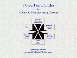
Introduction to G-Code Programming Computer Integrated Manufacturing. Unit 2: CNC Machining. In this lesson:. Review Coordinate Geometry Basics Identify common Terminology Examine G and M - Code language Provide opportunities for Review and Practice . A. (X,Y).

E N D
Introduction to G-Code Programming Computer Integrated Manufacturing Unit 2: CNC Machining
In this lesson: • Review Coordinate Geometry Basics • Identify common Terminology • Examine G and M - Code language • Provide opportunities for Review and Practice
A (X,Y) Rectangular Coordinate System Y-axis (1,.875) X-axis Origin .125 inch spacing
Ordered Pairs (1.000,1.000) A (-1.125,.625) B C D (.750,-1.000) (-.375,-.500)
3D Coordinate System (X,Y,Z) Z-axis Y-axis X-axis
Basic Machine Axes: 3 axis • Milling Machines: 3 axis X – axis (table left and right) Y – axis (table in and out) Z – axis (usually the spindle axis)
Additional Axes • A – axis (angular axis about X - axis) • B – axis (angular axis about Y – axis) • C – axis (angular axis about Z – axis) • U – axis (secondary axis parallel to X) • V – axis (secondary axis parallel to Y) • W – axis (secondary axis parallel to Z)
Terminology • NC – Numerical Control • CNC – Computer Numerical Control • DNC – Direct Numerical Control • APT – Automatic Programmed Tool • CAD – Computer Aided Design • CAM – Computer Aided Manufacturing • CIM – Computer Integrated Manufacturing
Download Code Sheet Click here to open Code Sheet
G - Code Programming • G – Code Programming • Originally called the “Word Address” programming format. • Processed one line at a time sequentially.
Common Format of a Block Sequence # Preparatory Function Dimension Words Feed Rate Spindle Function Tool Function Misc. Function N50 G90 G01 X1.40Y2.25 F10 S1500 T01 M03 Individual Words
Word Address 1 Reserved Code Words Worksheet N – Sequence or line number G – Preparatory function Dimension Words: X – Y – Z – • N – Sequence or line number • A tag that identifies the beginning of a block of code. It is used by operators to locate specific lines of a program when entering data or verifying the program operation. • G – Preparatory function • G words specify the mode in which the milling machine is to move along its programmed axes.
Word Address 2 • Dimension Words X – Distance or position in X direction Y – Distance or position in Y direction Z – Distance or position in Z direction • M – Miscellaneous functions • M words specify CNC machine functions not related to dimensions or axial movements.
Word Address 3 • F – Feed rate(inches per minute or millimeters per minute) • Rate at which cutting tool moves along an axis. • S – Spindle speed(rpm – revolutions per minute) • Controls spindle rotation speed. • T – Tool number • Specifies tool to be selected.
Word Address 4 • I – Circular cutting reference for x axis • J – Circular cutting reference for y axis • K – Circular cutting reference for z axis
G Word • G words or codes tell the machine to perform certain functions. Most G words are modal which means they remain in effect until replaced by another modal G code.
Common G Codes • G00– Rapid positioning mode • Tool is moved along the shortest route to programmed X,Y,Z position. Usually NOT used for cutting. • G01 – Linear Interpolation mode • Tool is moved along a straight-line path at programmed rate of speed. • G02 – Circular motion clockwise (cw) • G03 – Circular motion counter clockwise (ccw)
Common G Codes, con., • G17 – XY plane • G18 – XZ plane • G19 – YZ plane • G20 – Inch Mode • G21 – Metric Mode • G28 – Return to axis machine Zero (Home)
G Codes: G90, G91 • G90 – Absolute Coordinate Reference • References the next position from an absolute zero point which is set once for the entire program. • G91 – Incremental Coordinate Reference • References the next position from the previous position.
G Codes: Canned Cycles • G80 – Cancel canned cycle • G81 – Drilling cycle • G83 – Peck drilling cycle • G84 – Tapping cycle • G85 – Boring cycle • G86 – Boring cycle • NOTE: A canned cycle stays in effect until cancelled by a G80.
Canned Cycles: G81 • G81–Drilling Cycle • Feed to depth, rapid return • Example of program code: • N35 G81 X.500Y.500Z-1.000 R.100 F1.50 • N36 X1.000Y1.500 • N37 X1.500Y2.000 • N38 G80
Canned Cycles: G83, G84 • G83 – Peck Drilling Cycle • Feed to an intermediate depth, rapid out, rapid back to just above previous depth, feed to next depth, rapid out, repeat until reaching full depth. • G84 – Tapping Cycle • This cycle creates internal threads in an existing hole. • NOTE: One cannot over-ride the feed rate.
Canned Cycles: G85, G86 • G85 - Boring Cycle • Feed to depth, feed back out. • G86 – Boring Cycle • Feed to depth, rapid out.
G Codes: Cutter Compensation • G40 – Cancel cutter diameter compensation. • G41 – Cutter compensation left. • G42 – Cutter compensation right.
M Word • M words tell the machine to perform certain machine related functions, such as: turn spindle on/off, coolant on/off, or stop/end program. Professional Development ID Code: 6006
Common M words • M00 – Programmed pause • Automatically stops machine until operator pushes a button to resume program. • M01 – Optional stop • A stop acted upon by the machine when operator has signaled this command by pushing a button. • M02 – End of program • Stops program when all lines of code are completed. Must be last command in program.
Common M words • M03 – Turn spindle on • In clockwise direction • M04 – Turn spindle on • In counter clockwise direction • M05 – Stop spindle • Usually used prior to tool change or at end of program. • M06 – Tool change • Stops program and calls for a tool change, either automatically or manually.
Common M words • M08 – Turns Accessory 1 on. • M09 – Turns Accessory 1 off. • M10 – Turns Accessory 2 on. • M11 – Turns Accessory 2 off. • M30 – End of program • Similar to M02 but M30 will also “rewind” the program. Must be last statement in program. If used, DO NOT use M02.
Zero Points • Part Zero • Used for absolute programming mode. • Usually a position on the part that all absolute coordinates are referenced to. • Changes with different parts and programs. • Machine Zero or Machine Home Position • Fixed for each machine from the manufacturer. • Not changeable.
Cutter Path Generation • Cutter path is generated by moving the tool from point to point. The points are previously defined from the part drawing dimensions. • Each line of code will show the destination point of where the tool will go to.
Interpolation • Method of determining intermediate points along a cutting path. • Two methods: • Linear interpolation – cut a path along a specified angle at a specified feed rate. • Circular interpolation – cut a path along an arc or circle at a specified feed rate.
Axis movements: Caution! • Multiple axis movements are possible. • “Best Practice” is NOT to make a 3-axis movement using one line of code. • Move to position using two axes, X,Y; then move the Z with an additional line of code.
Top View NC Block .125 GRID SPACES Origin (0,0)
Download Worksheet Click here to open Practice Exercises
.125 GRID SPACES D( , ) I( , ) J( , ) K( , ) B( , ) L( , ) E( , ) A( , ) F( , ) C( , ) G( , ) H( , ) Origin (0,0) Worksheet Problem 1
Example 1: Program NC • N01 G90 G80 T00 • N02 G00 X0 Y3.000 Z1.000 • N03 M03 S1000
Example 1: Program NC • N01 G90 G80 T00 • N02 G00 X0 Y3.000 Z1.000 • N03 M03 S1000 • N04 X.375 Y.250 Z1.000 • N05 Z.100 • N06 G01 Z-.100 F5.00 • N07 Y1.750
Example 1: Program cont’d • N08 X1.250 Y.250 • N09 Y1.750 • N10 G00 Z.100 • N11 X2.625 Y.500 • N12 GO1 Z-.100 • N13 X2.375 Y2.50 • N14 X2.000
Example 1: Program cont’d • N15 X1.750 Y.500 • N16 Y1.500 • N17 X2.000 Y1.750 • N18 X2.375 • N19 X2.625 Y1.500
Example 1, con., • N20 G00 Z1.000 • N21 X0 Y3.000 • N22 M05 • N23 M30
Worksheet Problem 2 .250 GRID SPACE Origin
M( , ) F( , ) J( , ) I( , ) K( , ) O( , ) C( , ) B( , ) Q( , ) E( , ) A( , ) L( , ) P( , ) D( , ) G( , ) N( , ) H( , ) Origin .250 Grid Space Example 2: Top View
Example 2: PLTW • N01 G90 G80 T01 • N02 G00 X0 Y0 Z1.000 • N03 M03 S1000 • N04 X.750 Y.500 Z1.000 • N05 Z.100 • N06 G01 Z-.250 F5.00 • N07 Y2.500
Example 2: PLTW cont’d • N08 X1.250 • N09 G02 X1.250 Y1.500 I1.250 J2.000 • N10 G01 X.750 • N11 G00 Z.100 • N12 X2.250 Y2.500 • N13 G01 Z-.250 • N14 Y.500
Example 2: Program cont’d • N15 X3.250 • N16 G00 Z.100 • N17 X4.000 • N18 G01 Z-.250 • N19 Y2.500 • N20 X3.500 • N21 X4.500