Download

1 / 28
290 likes | 453 Vues
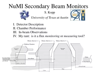
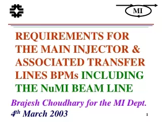
NuMI BEAM POSITION MONITOR via MAIN INJECTOR, and RECYCLER. Brajesh Choudhary, 06.Mar.2003 MINOS Collaboration Meeting University of South Carolina, Columbia. FERMILAB ACCELERATOR COMPLEX. Booster Circumference 474.2m. Booster Harmonic No. 84 . NuMI.

E N D
NuMI BEAM POSITION MONITORviaMAIN INJECTOR,and RECYCLER Brajesh Choudhary, 06.Mar.2003MINOS Collaboration MeetingUniversity of South Carolina, Columbia.
FERMILAB ACCELERATOR COMPLEX Booster Circumference 474.2m. Booster Harmonic No. 84 NuMI MI/Boster Circumference 3319.42m (474.2m•7) MI harmonic No. 84•7=588 TeV Circumference 2000 m TeV Harmonic No. 84•13.25
MAIN INJECTOR BASICS • The Fermilab MI is a synchrocyclotron which accelerates: • Protons from 8.9GeV to 120GeV, for • anti-proton production • low intensity slow resonant extraction (slow spill) for test beam • high intensity slow spill for dedicated kaon experiments • high intensity fast single turn extraction for NuMI/MINOS • Protons from 8.9Gev to 150GeV for collider operation, and • Anti-protons from the Accumulator and the Recycler (when integrated) from 8.9GeV to 150GeV for collider operation. Only 6 Booster cycles are utilized to fill the MI, allowing rest of the space for the abort gap.
RECYCLER RING BASICS • Recycler Ring is an 8 GeV storage ring constructed using permanent magnets. It is expected to increase the Tevatron collider luminosity in two ways: • Maintain high anti-proton production rate in the Accumulator by periodically sending the anti-proton stack to the Recycler, and • By recycling the left over anti-protons from the Tevatron to the Recycler and further cooling it, before injecting again in the Tevatron. [May Not Happen - AAC has advised against it – 4-6, Feb 2003.]
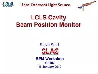
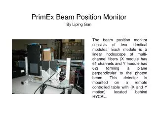
WHAT IS A BPM? • A beam position monitor is a non-intercepting device, used in particle accelerators and beam lines to measure the beam position by processing the beam induced signal on the pickup electrodes. • In the limit of very high beam energy, the fields are pure transverse electric and magnetic(TEM). So, if a beam is displaced from the center of a hollow conducting enclosure, the magnetic and electric fields are modified accordingly. Detailed knowledge of how the magnetic and electric fields depend on the beam position allows accurate determination of the beam position. • A conventional beam position monitor has a pair of electrodes (or 2 pairs, if 2 beam position coordinates are to be measured) on which signals are induced. The ratio of the amplitudes of the induced signals at the carrier frequency, either the beam-bunching frequency or a harmonic, is uniquely related to the beam position.
WHY DO WE NEED A PRECISION BPM SYSTEM? • A precision BPM system is needed to: • Reproducibly center the orbit in the physical aperture of the machine, thereby maximizing acceptance (1mm position error leads to 10% loss in aperture) • Verify stable orbit position from day to day, ensuring stable tuning condition • Have an accurate turn by turn measurement (ex: to measure lattice function of the machine, non-linear properties of the lattice, injection oscillation etc. etc.) • Understand geometrical and optical defects in the ring in terms of a calibrated geometrical survey • Understand and interpret the results of a beam experiments which are expected to produce static or transient beam orbit changes (pinging, orbit bumps, synchrotron oscillation, understanding the kicker behavior for NuMI) • Monitor and adjust the beam position in the injection and extraction lines, and the single turn orbit between the lambertson and the kicker in the ring • Independently measure orbit closure and injection oscillations.
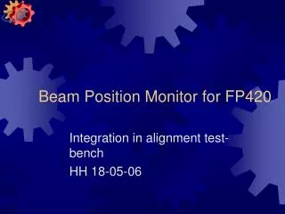
RECYCLER BPMs End View 4.4cm Top View 9.6cm 30cm Split tube BPM Design Pictures - Courtesy Jim Crisp
MI BPMs Large Aperture BPM Long face outer/inner size 4.75”/4.625” Short face outer/inner size 2.1”/1.9” MI Ring BPM Plate diameter outer/inner 4.75”/4.625”
NuMI SPLIT PIPE BPMs Target BPM Transport BPM
BPMs TO BE UPGRADED • In the RR we need to upgrade 104 horizontal and 107 vertical beam position monitors. We also need to upgrade 26 BPMs in the associated transfer lines. The total estimated cost is about $920K. (Phyics requirements defined + Technology approved + Purchase Order placed) • In the MI, we need to upgrade 203 ring BPM and 5 large aperture BPM. We also need to upgrade 64 BPM in MI8 line, 16 BPM in A1line, 15 BPM in P1 line and 11 BPM in P2 line. The total estimated cost will be ~$1.2M. (Physics requirements defined.) • NuMI needs only 26 BPM. The estimated cost will be around $100K. (Physics requirements defined.)
WHY UPGRADE MI BPM? • Present MI BPM electronics is blind to 2.5MHz time structure, and unreliable for position measurement of a single coalesced 53MHz bunch, as well as for 20-30 bunches of 53MHz beam. • The system is quite limited. It is essentially a single user, single buffer system. The data in the buffer gets overwritten every time any valid MI reset occurs. • The system is self (beam intensity threshold) triggered. It does not have a general purpose beam synch clock based trigger. • The system has limited resolution (beyond 10 mm) because of the non-linearity of AM to PM detection, the BPM geometry, and the 8-bit ADC used in the present electronics. • The firmware is written in Z80 machine code, which is now obsolete. Only one person (Alan Baumbaugh) at the laboratory is familiar with the code. Sharon Lackey used it ~15yrs ago for switchyard, and if it is really needed she can be called to help. • The system is 20+ years old and is approaching its end-of-life.
WHAT IS NEEDED ? • The MI BPM electronics should be functional at 2.5MHz, & 53MHz time structure. It should be reliable for position measurement either with a single Booster bunch, or a single coalesced bunch (53 MHz), as well as with multiple bunches, and multiple batches in the MI. • The system should be event driven to support multi-user with multi-buffer, so that different type of data can be taken during the same MI cycle, and the data taken with a particular MI reset does not overwrite the data taken with other MI reset. • Attenuation due to varying cable lengths, limits the “dynamic range” of the system and thus detection of small bunch intensities. Gain should be adjusted to account for this variation. • The system should at user option be self (beam intensity threshold) triggered as well as beam synch. clock triggered. • The present(old) multi-bus based system with 8-bit ADC computer interface should be replaced by a modern and better supported architecture (for ex: with a VME contained system) using 12/14-bit ADCs (for a bit resolution of ~50mm) .[Engineers to determine how this condition will be met].
WHAT DO WE NEED TO MEASURE? • We need to measure: • Beam Position at every BPM • Beam Intensity at every BPM, and • Calibrate every BPM properly.
DESIGN RESOLUTION – MI BPM Measured Resolution for beam position ± 5mm varies between ~50-150 mm. Lets preserve the level of resolution.
DYNAMIC RANGE FOR MI The BPM system should be capable of measuring beam position with 6 batches in the MI. DYNAMIC RANGE OF 24
BPMs in NuMI BEAM LINE • The NuMI beam line will have a total of 26 BPMs • A large aperture BPM with 6” long plates and a 4.625” aperture, at Q608 near Lambertson, • 21 split pipe BPM called the transport BPM. The outer/inner diameter of the split pipe is 4”(10.1cm)/3.875”(9.8cm, aperture) , and • 4 split pipe BPM called the target BPM. The outer/inner diameter of the split pipe is 2.125”(5.4cm)/2”(5.1cm, aperture) • The position accuracy, and the stability(calibration) requirement for the transport and target BPM differ (as shown in table later). • Every BPM needs to measure the beam position individually for each batch of the proton beam. • For at least one house (for the 4 target BPM), the BPM system should be capable of making multiple measurements within at-least one batch of the proton beam.
NuMI MEASUREMENT PRECISION/BATCH (3 REQUIREMENT) If the transport BPM meets the MI BPM precision requirement, NuMI will be satisfied.
NuMI PRECISION • The precision for “Transport BPM” comes from the knowledge of beam control requirements based on previous usage of ‘Autotune’ beam control, as to be used in NuMI. For example, the corresponding numbers for some experiments were: • Switchyard system - activate tuning for 0.4 mm deviation from nominal (0.2 mm for septa lineup); then, correct to < 0.2mm (0.1 mm) accuracy. (NuMI has no septa). • KTeV (with a very large targeting optics magnification) - activate for 1.0 mm deviation along the transport (0.05 mm deviation at target) The precisions were determined initially from detailed calculations of error functions using transport matrices, and verified in beam operation. • The precision for “Target BPM” comes from MINOS target width of 6.4mm, and the upstream baffle beam hole diameter of 11mm.
DIGITAL DOWN CONVERSION • Sample the waveform at a fixed sampling rate. • Multiply the sample by sine and cosine function of the bunch frequency (I and Q) and integrate over a fixed gate. • The signal strength measurement I2+Q2 is independent of the phase of the signal. • Tested with EchoTek 814, 8 channel 60MHz 14bit A/D’s • AD6620 Digital Receiver – Digital mixer followed by 3 digital filters (for integration and smoothing of the edges). • VME format • Like digital radio – Can be tuned to receive essentially any frequency 89KHz, 2.5MHz, and 53 MHz.
IN-PHASE & QUADRATURE SAMPLING “A - B” gives bunch-by-bunch “in-phase” signal “D - (C+E)/2” gives bunch-by-bunch “out-of-phase” or “quadrature” signal Vector Sum sqrt(I**2 +Q**2) is insensitive to clock jitter Argument for sampling at 4 X Frequency to be sampled Courtesy : BILL FOSTER
DDC TEST RESULTS WITH 53MHz BEAM Sampling of 84 consecutive 53MHz(19ns) waveform at every 17ns (60MHz clock). One would like to sample at twice or more of the frequency rate. Ideally at 106MHz+. Best at 212MHz.Under Sampled. But due to long train of pulses (84 bunches) one can get away with under sampling. Raw ADC Sample Number – 17ns sampling Courtesy: WARREN SCHAPPERT
DDC TEST RESULTS WITH 53MHz BEAM • The measurement was done in MI54 line, in front of MiniBoone hall. • Beam moving around. • Measured resolution is 0.18% of the aperture. • Intrinsic resolution of the BPM will be better than the number presented here. Batch Position (Average of 84 Bunches) Courtesy: WARREN SCHAPPERT
DDC TEST RESULTS WITH 53MHz BEAM • Resolution is limited due to beam motion. • Intrinsic resolution of the BPM better than measurement presented here. • Being worked upon. Moving Beam Courtesy: WARREN SCHAPPERT
MEASUREMENT PRECISION WITH DDC IN THE RECYCLER • Beam Position Measurement Precision with 2.5MHz Beam Structure for IBEAM = 1.24E11 • Measured RMS = 10 – 20 mm • The beam position is very stable for repeated injection with different beam currents.
SCHEDULE and SUMMARY SCHEDULE: • NuMI time frame is independent of MI needs. The technology decision for the NuMI BPM must be taken before the DOE review in 6/2003, and the system should be ready by the spring of 2004. SUMMARY: • NuMI BPM physics requirements have been defined. It is needed to commission the beam line, and will be ready in time.