Download
1 / 44
440 likes | 443 Vues
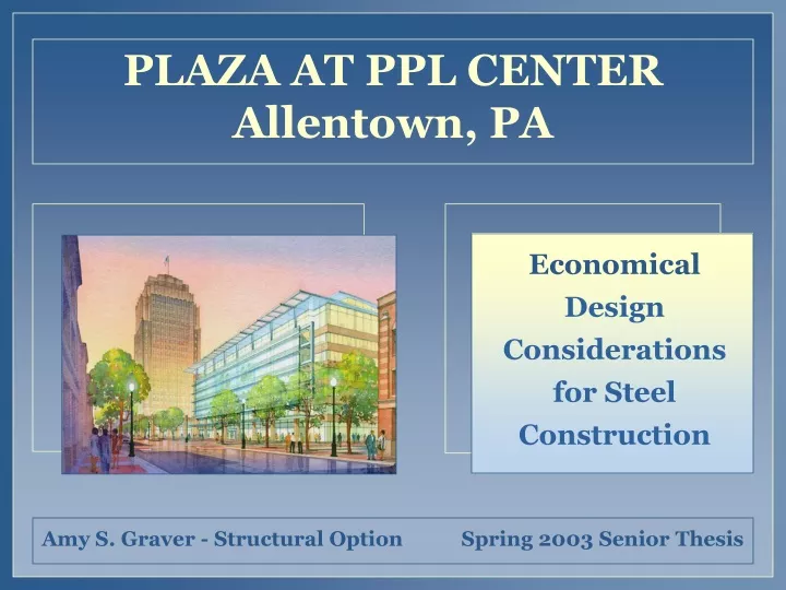
This presentation explores the economical design considerations for the PPL EnergyPlus building, including moment frame comparisons, braced frame design, and composite floor evaluation.

E N D
INTRODUCTION PRESENTATION OUTLINE • Introduction • Economical Design Considerations • Moment Frame Comparisons • Braced Frame Design • Composite Floor Evaluation • Mechanical Re-Design • Conclusions
INTRODUCTION PROJECT TEAM • Owner: Liberty Property Trust • Primary Tenant: PPL EnergyPlus • Architect and Landscape: Robert A. M. Stern Architects • Structural Engineers: Thornton-Tomasetti • MEP, Fire Protection: PPL Energy Services Mid-Atlantic, LCC • Construction Manager: L.F. Driscoll • Architect of Record: Kendall/Heaton Associates, Inc. • Civil Engineers: Pennoni Associates • Lighting Consultant: Quentin Thomas Associates, Inc.
INTRODUCTION LOCATION LINDEN STREET LINDEN STREET NORTH BUILDING PROPOSED PARKING GARAGE N. EIGHTH STREET N. TENTH STREET N. NINTH STREET PLAZA AT PPL CENTER TOWER AT PPL CENTER HAMILTON STREET HAMILTON STREET
INTRODUCTION BUILDING FACTS • Size • $29 million base building cost, $19 million tenant specific costs • 256,000 sq. ft. • 200,000 sq. ft. to be leased by PPL Corporation • Uses • 8-story Multi-use Building • First Floor: Retail Space • Floors 2-6: Office Space for PPL EnergyPlus • Floors 7-8: Energy Securities Trading Floors
INTRODUCTION BUILDING FACTS • Architecture • LEED Gold Certification • Central Atrium • Winter Gardens • and Roof Top Garden • Glass Façade with Strips of • Pre-cast Concrete Panels
INTRODUCTION STRUCTURE • Foundation • Partial Basement w/ Poured Concrete Walls • Continuous Concrete Spread Footings • Gravity System • Composite Steel Beams • Composite Deck • 14’-20’ Stories • 30’x42’ Bays • Typical Sizes • Beams: W18 • Columns: W14
INTRODUCTION STRUCTURE • East-West: Moment Frames • North-South: Braced Frames Lateral System A B C Moment Frames B/C D Moment Frame A Moment Frame D
ECONOMY PRESENTATION OUTLINE • Introduction • Economical Design Considerations • Moment Frame Comparisons • Braced Frame Design • Composite Floor Evaluation • Mechanical Implications • Conclusions
ECONOMY CONSIDERATIONS • Low Seismic Design • Braced Frames • Partial Composite Construction % of Construction Costs % of Construction Costs
MOMENT FRAME COMPARISONS PRESENTATION OUTLINE • Introduction • Economical Design Considerations • Moment Frame Comparisons • Braced Frame Design • Composite Floor Evaluation • Mechanical Re-Design • Conclusions
MOMENT FRAME COMPARISONS SEISMIC DESIGN • Allentown, PA • Not Considered a High Seismic Area • Seismic Design Category B • Under More Recent Codes • Seismic Can Control • Subject to Seismic Provisions when R>3
MOMENT FRAME COMPARISONS SEISMIC DESIGN • Ductility • Lower Base Shear with Increased Ductility • Response Modification Factor • To account for ductility of a system • Cs is indirectly proportional to R • Since V= CsW, a lower R-Factor corresponds to a higher base shear
MOMENT FRAME COMPARISONS SEISMIC DESIGN • Applied Code: IBC 2000 • References AISC Seismic Provisions & Supplement 1 • Connections must be designed by Seismic Provisions if R>3 • AISC Seismic Provisions for Structural Steel Buildings • Connections must be stronger than connected members • Classifies moment frames based on a rotation criteria
MOMENT FRAME COMPARISONS DESIGN STATEMENT • Connection Moment Capacity per AISC • Mp • Mp • 1.1RyMp • Mu • Connection Moment Capacity per FEMA 350 • 1.1RyMp • 1.1RyMp • 1.1RyMp • Mu • Response Modification Factor • R=8 • R=6 • R=4 • R=3 • Four Types of Moment Frames • Special Moment Frames (SMF) • Intermediate Moment Frames (IMF ) • Ordinary Moment Frames (OMF) • Steel Systems not Detailed for Seismic Resistance • Required Rotation • θ=0.4 radians • θ=0.2 radians • None • None
MOMENT FRAME COMPARISONS DESIGN STATEMENT • Comparison • SMF • IMF • OMF • R=3 Differences Results Increasing Base Shear Less Stringent Detailing Smaller Connections More Economical Faster Construction Decreasing R-Factor Larger Members
MOMENT FRAME COMPARISONS CONNECTIONS • Connection Design • FEMA 350: rotation criteria • SMF & IMF • LRFD Manual: strength design • OMF & R=3 • Web-Bolted, Flange-Bolted Connections • Approved for Seismic Use • Tested by Federal Emergency • Management Agency (FEMA) • Meets Rotation Requirements • for SMF and IMF
MOMENT FRAME COMPARISONS COST COMPARISON • Included Costs • Material Costs • Fabrication Labor • Erection Labor • Excluded Costs • Quality Inspection • Special Fabrication Procedures
MOMENT FRAME COMPARISONS CONNECTION COMPARISON Moment Frame A Strong Column, Weak Beam Deeper Beams Actual Loads Design Capacity of Members Smaller Members SMF Heavier Columns R=3 W18x60 W14x74 W14x99 W24x62
MOMENT FRAME COMPARISONS COMPARISON
MOMENT FRAME COMPARISONS SCHEDULE EFFECTS • 1000 hrs. of Fabrication Time • Cost of Stiffeners • Saves 3 weeks • Critical Path • Added Float • Start Later • Erection • Remains on Critical Path • Dependent on Sitework • and Foundation 3 weeks
BRACED FRAME ANALYSIS PRESENTATION OUTLINE • Introduction • Economical Design Considerations • Moment Frame Comparisons • Braced Frame Design • Composite Floor Evaluation • Mechanical Re-Design • Conclusions
BRACED FRAME DESIGN DESIGN STATEMENT • Results of the Moment Frame Comparison • Low Seismic is More Economical • Connections Drive Cost • Try Braced Frames in East-West Direction • Eliminates 410 Moment Connections • Works Within the Proposed Floor Plan
BRACED FRAME DESIGN ARCHITECTURE • Chevron Braced • Adequate for Proposed Openings • 14’ Minimum Floor-to-floor Height • Accommodates a Double Door • Tenant Fitout • Rooms along • column grids • 30-year lease • Try Braced Frames
BRACED FRAME DESIGN FLOOR PLANS Proposed Braced Frames Existing Moment Frames
BRACED FRAME DESIGN DESIGN • Seismic is the Governing Lateral Force for Members • Concentric Braced Frame • R=3 • V=1182K • Typical Sizes • W14 Columns and Braces to Match North-South Direction • W24x68 Beams
BRACED FRAME DESIGN COST COMPARISON • Included Costs • Moment frame members now sized for gravity only • Additional cost of connections above a typical shear connection
BRACED FRAME DESIGN SCHEDULE Project Complete: April 30, 2003 • Additional Time Savings • Fabrication • Not on the critical path • Adds 3 weeks of float • Erection • On the critical path • Project Completion: 3 weeks earlier Project Complete: April 12, 2003
COMPOSITE FLOOR EVALUATION PRESENTATION OUTLINE • Introduction • Economical Design Considerations • Moment Frame Comparisons • Braced Frame Design • Composite Floor Evaluation • Mechanical Re-Design • Conclusions
COMPOSITE CONSTRUCTION DESIGN STATEMENT • Cost of 1 Shear Stud = 10lbs. of Steel • $0.50 Material Cost • $1.50 Labor Cost • Try Partial Composite • Is a heavier beam with fewer shear studs more economical?
COMPOSITE CONSTRUCTION FLOOR PLANS • Floors 2-6 Existing: 100% Composite Re-design: 90% Composite W18x35 [48] W18x35 [44]
COMPOSITE CONSTRUCTION FLOOR PLANS • Floors 1, 7-8 Existing: 100% Composite Re-design: 40% Composite W18x40 [48] W21x44 [24]
COMPOSITE CONSTRUCTION COMPARISON Total Building Savings
MECHANICAL RE-DESIGN PRESENTATION OUTLINE • Introduction • Economical Design Considerations • Moment Frame Comparisons • Braced Frame Design • Composite Floor Evaluation • Mechanical Re-Design • Conclusions
MECHANICAL EFFECTS DESIGN STATEMENT • Composite Beam Comparison • W18 to W21 • 3” decrease in usable ceiling plenum • Original Design • 28”x12” SA duct below beams • Air Flow Rate = 2500CFM • Air Velocity = 1150FPM • Static Pressure Drop = 0.1in.w.g.
MECHANICAL EFFECTS RE-DESIGN • Initial Size Problems • 9” duct height is required to maintain existing plenum • To supply 2500CFM at 0.1in.w.g., • 42”x9” required • Does not meet the 4-to-1 width-to-height ratio
MECHANICAL EFFECTS SOLUTION • Design • 2500CFM First 16’ • 1900CFM Past Branch • Results • Turning Vanes in Elbow • 4-to-1 Ratio past Branch • Maintains Design Criteria 34”x9” 42”x9” 600CFM VAV Box
MECHANICAL RE-DESIGN PRESENTATION OUTLINE • Introduction • Economical Design Considerations • Moment Frame Comparisons • Braced Frame Design • Composite Floor Evaluation • Mechanical Re-Design • Conclusions
CONCLUSIONS ECONOMY • Cost Savings • Moment Frames with R=3 . . . $22,000 • Braced Frames . . . . . . . . . . . $100,000 • Composite Construction . . . . . $5,300 • Time Savings • Moment Frames with R=3 . . . Fabrication: 3 weeks • Braced Frames . . . . . . . . . . . Fabrication: 6 weeks • . . . . . . . . . . . Erection: 3 weeks
CONCLUSIONS RECOMMENDATIONS • Braced Frames are Most Economical Lateral System • Feasible with architectural layout • $100,000 cost savings • Project Completion: 3 weeks earlier • Deeper, Heavier Beams with Less Composite Action • Increases floor depth • Ceiling plenum height retained with shallower duct
CONCLUSIONS ACKNOWLEDGMENTS • A huge thank you to everyone one who answered questions, provided information and offered support… your time and efforts are greatly appreciated. • Pennoni Associates: Civil Engineer • Frank Adams, P.E., AIA • Jeff Ott, P.E. • Ed Sander, P.E. • The Adams Division • Thornton-Tomasetti: Structural Engineer • Hi Sun Choi, P.E. • L.F. Driscoll: Construction Manager • Ed Jackowski • Stewart-Amos Steel • Curt Zeigler • AE Faculty • Dr. Hanagan, P.E. • Walt Schneider, P.E. • Professor Parfitt, P.E. • Jonathan Dougherty • AE Class of 2003 • Rebecca Mittel • Melissa Rosol • My Family and Friends • Last but certainly not least…
CONCLUSIONS ? QUESTIONS
CONCLUSIONS ? QUESTIONS
MECHANICAL EFFECTS RESULTS • Higher Air Velocity to Maintain Air Flow Rate • Increased noise through diffusers • Not a large enough increase to impact occupants • Duct meets industry standard for 4-to-1 ratio