Download
1 / 46
540 likes | 877 Vues
Volume Rendering. Lecture 21. Acknowledgements. These slides are collected from many sources. A particularly valuable source is the IEEE Visualization conference tutorials. Sources from:

E N D
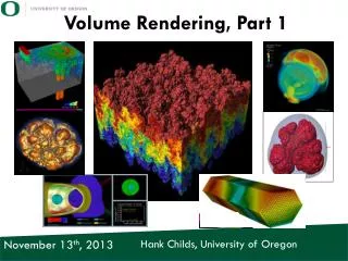
Volume Rendering Lecture 21
Acknowledgements • These slides are collected from many sources. • A particularly valuable source is the IEEE Visualization conference tutorials. • Sources from: Roger Crawfis, Klaus Engel, Markus Hadwiger, Joe Kniss, Aaron Lefohn, Daniel Weiskopf, Torsten Moeller, Raghu Machiraju, Han-Wei Shen and Ross Whitaker R. Crawfis, Ohio State Univ.
Visualization of Volumetric Data • Direct volume rendering of scalar fields • Flow visualization in 3D • Focus on regular grids R. Crawfis, Ohio State Univ.
Visualization of Volumetric Data R. Crawfis, Ohio State Univ.
Surface Graphics • Traditionally, graphics objects are modeled with surface primitives (surface graphics). • Continuous in object space R. Crawfis, Ohio State Univ.
Difficulty with Surface Graphics • Volumetric object handling • gases, fire, smoke, clouds (amorphous data) • sampled data sets (MRI, CT, scientific) • Peeling, cutting, sculpting • any operation that exposes the interior R. Crawfis, Ohio State Univ.
Volume Graphics • Defines objects on a 3D raster, or discrete grid in object space • Raster grids: structured or unstructured • Data sets: sampled, computed, or voxelized • Peeling,cutting … are easy with a volume model R. Crawfis, Ohio State Univ.
Volume Graphics & Surface Graphics R. Crawfis, Ohio State Univ.
Volume Graphics - Cons • Disadvantages: • Large memory and processing power • Object- space aliasing • Discrete transformations • Notion of objects is different R. Crawfis, Ohio State Univ.
Volume Graphics - Pros • Advantages: • Required for sampled data and amorphous phenomena • Insensitive to scene complexity • Insensitive to surface type • Allows block operations R. Crawfis, Ohio State Univ.
Volume Graphics Applications (simulation data set) • Scientific data set visualization R. Crawfis, Ohio State Univ.
More Volume Graphics Applications (artistic data set) • Amorphous entity visualization • smoke, steam, fire R. Crawfis, Ohio State Univ.
How to visualize? slice • Slicing: display the volume data, mapped to colors, along a slice plane • Iso-surfacing: generate opaque and semi-opaque surfaces on the fly • Transparency effects: volume material attenuates reflected or emitted light Semi-transparentmaterial Iso-surface R. Crawfis, Ohio State Univ.
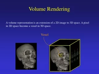
Volume Data Continuous scalar field in 3D • Discrete volume:voxels • Sampling • Reconstruction R. Crawfis, Ohio State Univ.
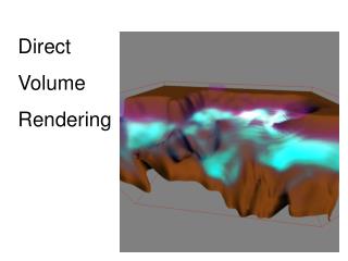
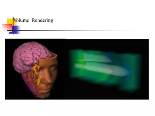
Direct Volume Rendering • Render volume without extracting any surfaces (DVR) • Map scalar values to optical properties(color, opacity) • Need optical model • Solve volume renderingintegral for viewing raysinto the volume R. Crawfis, Ohio State Univ.
Direct Rendering Pipeline I • Detection of Structures • Shading • Reconstruct (interpolate/filter) color/opacity • Composite • Final Image Validation (change parameters) R. Crawfis, Ohio State Univ.
Direct Rendering Pipeline ClassifyShade Reconstruct Visibilityorder Composite Validate R. Crawfis, Ohio State Univ.
Classification How do we obtain the emission and absorption values? scalar value s T(s) emission RGB absorption A R. Crawfis, Ohio State Univ.
Ray Traversal Schemes Intensity Max Average Accumulate First Depth R. Crawfis, Ohio State Univ.
Ray Traversal - First Intensity • First: extracts iso-surfaces (again!)done by Tuy&Tuy ’84 First Depth R. Crawfis, Ohio State Univ.
Ray Traversal - Average Intensity • Average: produces basically an X-ray picture Average Depth R. Crawfis, Ohio State Univ.
Ray Traversal - MIP Intensity • Max: Maximum Intensity Projectionused for Magnetic Resonance Angiogram Max Depth R. Crawfis, Ohio State Univ.
Maximum Intensity Projection (1) • No emission or absorption • Pixel value is maximum scalar value along the viewing ray • Advantage: no transfer function required • Drawback: misleading depth information • Works well for MRI data (esp. angiography) Maximum Smax Scalar value S s s0 ray R. Crawfis, Ohio State Univ.
Maximum Intensity Projection (2) Emission/Absorption MIP R. Crawfis, Ohio State Univ.
Ray Traversal - Accumulate Intensity • Accumulate: make transparent layers visible!Levoy ‘88 Accumulate Depth R. Crawfis, Ohio State Univ.
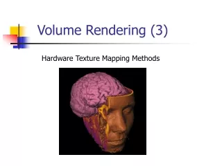
Texture-Based Volume Rendering Roger Crawfis
Texture-based Volume Rendering • Volume rendering by ray casting is time-consuming • one ray per pixel • each ray involves tracking through volume calculating samples, and then compositing • different for each viewpoint • Alternative approach - using texture maps - can exploit graphics hardware R. Crawfis, Ohio State Univ.
Modern graphics hardware includes facility to draw a textured polygon The texture is an image with red, green, blue and alpha components… … so several overlapping polygons can be composited Texture Mapping R. Crawfis, Ohio State Univ.
Texture-based Volume Rendering • Draw from back-to-front a set of rectangles • first rectangle drawn as an area of coloured pixels, with associated opacity, as determined by transfer function and interpolation - and merged with background in a compositing operation (supported by hardware) • successive rectangles drawn on top R. Crawfis, Ohio State Univ.
Texture-Based Volume Rendering Image Data Set Proxy Geometry R. Crawfis, Ohio State Univ.
For a given viewing direction, we would like to select slices perpendicular to this direction This requires interpolation to get the values on the slices 3D texture hardware supports tri-linear interpolation. Texture-based Volume Rendering volume image plane 3D texture mapping R. Crawfis, Ohio State Univ.
Texture-based Volume Rendering • Less-GPU intensive solution - 2D texture mapping: • view volume as set of slices parallel to co-ordinate planes choose the orientation best suited to viewing direction R. Crawfis, Ohio State Univ.
Render Proxy Geometry • No volumetric hardware primitives... • Stack of texture-mapped slices • Generate fragments: resample volume! R. Crawfis, Ohio State Univ.
Texture Mapping + Textured-mapped polygon 2D image 2D polygon R. Crawfis, Ohio State Univ.
(0,1) (1,1) (0,0) (1,0) Texture Mapping (2) (0,0.5) (0.5,0.5) (0,0) (0.5,0) assign the texture coordinates to each polygon to establish the mapping Each texel has 2D coordinates assigned to it. R. Crawfis, Ohio State Univ.
Texture based volume rendering R. Crawfis, Ohio State Univ.
2D Textured Slices (1) • Object-aligned slices • Three stacks of 2D textures • Bi-linear interpolation • Fast and simple, but consumes lots of memory R. Crawfis, Ohio State Univ.
z y x Three copies of data needed • Different input textures are needed for different view directions. • Reorganizing the textures on the fly is too costly. • Prepare the texture sets beforehand xz slices yz slices xy slices R. Crawfis, Ohio State Univ.
3D Texture Based Volume Rendering • View-aligned slices; clip slice geometry • Single 3D texture • Tri-linear interpolation R. Crawfis, Ohio State Univ.
3D Texture Based Volume Rendering • Texture Interpolation R. Crawfis, Ohio State Univ.
3D Texture Mapping Arbitrary slicing through the volume and texture mapping capabilities are needed - Arbitrary slicing polygon: this can be computed using software in real time This is basically polygon-volume clipping R. Crawfis, Ohio State Univ.
3D Texture Mapping Texture mapping to the arbitrary slices This requires 3D texture mapping hardware Input texture: volume (pre-classified and shaded) essentially an (R,G,B,a) volume Depending on the position of the polygon, appropriate textures are re-sampled, constructed and mapped to the polygon. R. Crawfis, Ohio State Univ.
(r2,s2,t2) (r3,s3,t3) (r1,s1,t1) (r0,s0,t0) Solid (3D) Texture Mapping Now the input texture space is 3D Texture coordinates: (r,s,t) (0,1,1) (1,1,1) (0,1,0) (1,1,0) (1,0,0) (0,0,0) R. Crawfis, Ohio State Univ.
Slice Based Rendering View direction 1 slice Slices 5 slices 20 slices 85 slices 45 slices 170 slices R. Crawfis, Ohio State Univ.
C. Lao, OSU Lighting and Shading • 3D texture mapping with hardware tricks to achieve lighting is now feasible. R. Crawfis, Ohio State Univ.
Lighting and Shading • Gradient estimation • Pre-computed gradients • On-the-fly gradients • Per-pixel illumination • Non-polygonal shaded isosurfaces • Volume shading • Pre-computed illumination R. Crawfis, Ohio State Univ.