Download
1 / 15
230 likes | 438 Vues
GPS Waypoint Navigation. Team M-2: Charles Norman (M2-1) Julio Segundo (M2-2) Nan Li (M2-3) Shanshan Ma (M2-4) Design Manager : Zack Menegakis. Presentation 2: Architecture Proposal January 30, 2006. Overall Project Objective:

E N D
GPS Waypoint Navigation Team M-2: Charles Norman (M2-1) Julio Segundo (M2-2) Nan Li (M2-3) Shanshan Ma (M2-4) Design Manager: Zack Menegakis Presentation 2: Architecture Proposal January 30, 2006 Overall Project Objective: Design a chip that navigates an aircraft to pre-determined waypoints.
Status • Design Proposal • Project chosen • Architecture Proposal • MATLAB simulated • Behavioral Verilog written • Behavioral Verilog simulated • Floorplan • Schematic Design • Layout • Simulations
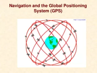
Application Description • We are designing a GPS based waypoint navigation system for use in an aircraft. • The system will be able to autopilot the craft through a series of user specified GPS coordinates in 3 dimensions.
Why Use a Chip? • Our system would be perfect for an Unmanned Aerial Vehicle (UAV) due to its light weight, low power consumption, low cost, and specific capabilities • The system is designed to do exactly what UAVs are best at: flying over an area in order to observe it. The UAV has many military and civilian applications.
System Flow • Inputs will consist of GPS waypoint coordinates for the vehicle itself taken from a satellite or given by a user. • The system will continually sample the position of the aircraft while holding the previous and current positions in memory • Calculate and output the course corrections that must be made in order to proceed toward the next destination. • Angle needed to hit next waypoint within 1 second (~106 feet) • Difference in current and destination altitudes needs to be within 15 feet. • Maximum speed must always be achieved.
Block Description • FSM Controller – Controls state flow in system • Setup mode • Navigation mode • Arrival mode • SRAM – Stores up to 5 GPS waypoint coordinate sets • Waypoint Reached Comparator – Decides whether the aircraft is sufficiently close to the next waypoint • Altitude Comparator – Compares current altitude to next waypoint’s altitude • Speed Comparator – Compares current speed to max speed • Speed Calculator – Calculates current speed at which the aircraft is traveling • Distance Calculator – Calculates distance between current position and next waypoint • Sexagesimal Degrees to Decimal Degrees Converter – Converts Degrees/Minutes/Seconds to Decimal Degrees • “Black Box” – Used to calculate arctan’s and squares for angle and speed calculations
module FSM (output reg control, output reg [2:0] counter, input [1:0] rw, input range, clk); reg [1:0] state, nextState; parameter A = 2'b00, //Navigate/read B = 2'b01, //Setup/write C = 2'b10, //No Op D = 2'b11; //Reset always @ * begin case (state) A: begin nextState = rw; if (range == 0) //not within range control = 1; //turn on all functions else //within range control = 0; //turn off all functions end B: begin nextState = rw; control = 0; //turn off all functions counter = counter + 1; end C: begin nextState = rw; end D: begin nextState = rw; control = 0; //turn off all functions counter = 0; end default: nextState = D; endcase // case(state) end always @(posedge clk) state <= nextState; endmodule // FSM Behavioral Verilog module Distance_cal (output [11:0] result, input [5:0] lat, lon); result = lat*lat+lon*lon; endmodule // Distance_cal module wp_comp ( output result , [22:0] lon_dif , [22:0] lat_dif, input [22:0] curlon, [22:0] curlat, [22:0] lat2, [22:0] lon2); [22:14] lat_dif = [22:14] lat2 - [22:14] curlat; [13:7] lat_dif = [13:7] lat2 - [13:7] curlat; [6:0] lat_dif = [6:0] lat2 - [6:0] curlat; [22:14] lon_dif = [22:14] lon2 - [22:14] curlon; [13:7] lon_dif = [13:7] lon2 - [13:7] curlon; [6:0] lon_dif = [6:0] lon2 - [6:0] curlon; if ( ([21:14] lat_dif == 0) && ([12:7] lat_dif == 0) && ([21:14] lon_dif == 0) && ([12:7] lon_dif == 0) ) result = 1; else result = 0; endmodule // wp_comp
Inputs / Outputs • Inputs • Latitude & Longitude Coordinates : 46 bits • Latitude : -180˚ to 180˚, Longitude : -90˚ to 90˚ • Degrees : 9-bit 2's complement • Minutes : 7-bit 2's complement • Seconds : 7-bit 2's complement • Speed :10-bit signed magnitude • Altitude : 15-bit unsigned • Mode : 2-bit unsigned • Outputs • Angle Correction : 9-bit signed magnitude • Speed Correction : 11-bit signed magnitude • Altitude Correction : 16-bit signed magnitude • Total • 109 bits
Design Decisions • Merge groups M2 & M3 since 3 people in each group left • Use a “black box” for the arctan and square functions • Each of these functions are projects by themselves • Increased accuracy • Implement speed and altitude calculator • Decrease number of GPS waypoint coordinate inputs from 10 to 5 to reduce SRAM by a factor of approximately 2 • Use 2’s Complement for representation for coordinates & Signed Magnitude for everything else • Sample current position every one second which allows for up to 16.99 seconds (distance) of change
Assumptions • Latitude & Longitude are always constant • In reality, longitude is not constant (ranges from 0 – 69 miles per degree) while latitude is usually 69 miles per degree • This is really not a factor anyway because, we usually doing computations on the seconds aspect of the coordinates • Altitude is independent of speed • The speed we are calculating refers to latitude and longitudinal directions • The plane will rise by a proportional amount determined by avionics • Achieve maximum speed at all times
Alternate Projects Considered • Parking garage management system • Guitar tuner/effects processor • Swimming pool monitor • Smart sensor system • Smart Refrigerator • PID Controller • Smart Watch
What’s Next… Here’s what’s on our agenda for next week… • Complete Verilog simulations • Decide types of adders, subtractors, etc. would be best for our design • Better estimate the size of our project and decide if we are able implement one or both of the operations of the “black box” • Implement countdown until arrival at next waypoint? • Additional functionality? • Structural Verilog & Initial Floorplan